
What Is Glass Electrical Insulators: Complete Guide to Applications, Performance & Industry Standards
What Is Glass Electrical Insulators:
Complete Guide to Applications, Performance & Industry Standards

Table of Contents
- Introduction to Glass Electrical Insulators
- What Exactly Is a Glass Electrical Insulator?
- Raw Material Composition and Manufacturing Process
- Types of Glass Electrical Insulators
- Electrical Properties and Performance Standards
- Advantages of Glass Insulators
- Disadvantages and Limitations
- Glass Insulators vs. Porcelain Insulators: Comprehensive Comparison
- Applications in Modern Power Systems
- Installation, Maintenance, and Safety Considerations
- Historical Development and Evolution
- Frequently Asked Questions (FAQ)
- Conclusion and Future Outlook
1.Introduction to Glass Electrical Insulators
In the complex infrastructure of modern electrical power systems, few components are as critical—yet often overlooked—as electrical insulators. Glass electrical insulators represent one of the most significant technological innovations in the history of electrical transmission and distribution. These engineered components serve as the silent guardians of power transmission lines, preventing dangerous electrical currents from following unintended paths and ensuring the safe, efficient delivery of electricity to millions of homes and businesses worldwide.
For over 180 years, since their initial deployment on telegraph lines in the 1840s, glass insulators have evolved from simple, basic devices into sophisticated, high-precision components that withstand extreme voltages, mechanical stresses, and harsh environmental conditions. Today, these insulators form an essential backbone of global electrical infrastructure, particularly in high-voltage transmission systems where reliability and performance are paramount.
The electrical industry has increasingly turned to glass insulators as the preferred solution for high-voltage applications, especially for transmission voltages exceeding 500 kilovolts. Unlike their porcelain counterparts, glass insulators offer superior electrical performance, transparent design for fault detection, and exceptional longevity without degradation over decades of service.
This comprehensive guide explores every dimension of glass electrical insulators—from their fundamental composition and manufacturing processes to their diverse applications, advantages, and performance characteristics. Whether you are an electrical engineer, utility professional, procurement specialist, or industry professional seeking deeper technical understanding, this resource provides the authoritative information necessary for informed decision-making.
2.What Exactly Is a Glass Electrical Insulator?
Fundamental Definition
A glass electrical insulator is a precisely engineered component manufactured from specially formulated, toughened glass that serves the dual purpose of providing electrical insulation while mechanically supporting electrical conductors in power transmission and distribution systems. The insulator's primary function is to prevent the flow of electrical current between conductive materials—such as live power line conductors—and grounded structures like utility poles, transmission towers, or equipment frames.
The word "insulator" derives from the Latin "insulatus," meaning isolated or separated. In electrical engineering, insulators are defined as materials that resist the flow of electric current. Unlike conductors, which readily permit electron flow, insulators maintain extremely high electrical resistance, ensuring that electricity flows only through intended pathways.
Glass insulators achieve this critical insulation through their composition of silica-based compounds arranged in a non-crystalline structure that exhibits extraordinarily high dielectric strength—the ability to withstand applied electric fields without electrical breakdown or puncture.
Physical Structure and Design
Typical glass insulators display a distinctive architectural design characterized by multiple functional zones:
Dome or Pin Head: The upper rounded section that provides mechanical connection points and helps shed water during rain or fog conditions.
Pin Hole with Internal Threads: The central opening equipped with precisely machined internal threads that allow mechanical attachment to a wooden, composite, or metal support pin mounted on utility poles or tower cross-arms.
Skirts and Sheds: Multiple external ridges or grooves extending downward from the main body that serve several critical functions. These features increase the surface creepage distance (the distance an electrical arc must travel along the insulator surface), enhance water shedding during rain events, and reduce the accumulation of contamination.
Drip Points: Small protrusions or angular sections along the lower portion designed specifically to prevent moisture and dust from collecting on the undersurface.
Glaze or Transparent Surface: The smooth, homogeneous glass exterior that provides both mechanical protection and transparency for visual inspection.
This elegant yet functional design has remained fundamentally unchanged for over a century, a testament to its inherent engineering excellence.
Material Classification: Why Glass?
Glass represents an optimal material choice for electrical insulation applications for several compelling reasons:
Electrical Superiority: Glass exhibits exceptional dielectric strength—approximately 140 kilovolts per centimeter (kV/cm)—compared to porcelain's 60 kV/cm. This superior performance permits thinner, lighter insulators that occupy less space on transmission structures while maintaining or exceeding electrical safety margins.
Transparency: Glass's inherent transparency allows visual inspection of internal defects, impurities, or structural damage. This characteristic is impossible with opaque materials, providing significant safety and maintenance advantages.
Homogeneity: Glass insulators are chemically and physically homogeneous throughout their entire structure—the material composition is uniform from surface to core. This uniformity contrasts sharply with porcelain insulators, where external glaze differs from internal ceramic, potentially creating internal weakness zones.
Aging Resistance: Glass insulators demonstrate remarkable property stability over time. The mechanical and electrical characteristics remain essentially unchanged after decades or even centuries of service, whereas porcelain can experience age-related degradation of electrical properties.
Environmental Resilience: The smooth glass surface resists accumulation of dust, salt, and pollution that would otherwise create conducting pathways for leakage currents. In coastal or industrialized regions with heavy contamination, glass insulators consistently outperform traditional ceramic alternatives.
3.Raw Material Composition and Manufacturing Process
Raw Material Selection and Preparation
The manufacturing of glass electrical insulators begins with careful selection and preparation of raw materials. The primary components include:
Silica Sand (SiO₂): Constituting approximately 70-75% of the final insulator composition, silica sand forms the fundamental glass matrix. Silica provides the structural foundation of the glass network and contributes significantly to dielectric strength and mechanical stability. Premium grades of silica sand with minimal iron oxide impurities are essential, as iron contamination would compromise electrical performance and alter the optical properties.
Soda Ash (Sodium Carbonate, Na₂CO₃): Added at approximately 12-15% by weight, soda ash functions as a flux—a substance that dramatically reduces the melting point of silica from approximately 1,700°C to a more economically feasible 1,400-1,600°C. This temperature reduction is critical for industrial scalability, reducing furnace energy consumption and equipment stress.
Limestone (Calcium Carbonate, CaCO₃): Comprising roughly 8-10% of the mixture, limestone enhances glass durability and weather resistance. Calcium ions in the glass structure improve resistance to moisture penetration and atmospheric corrosion.
Specialty Additives: Alumina (Al₂O₃) and magnesium oxide (MgO) are added in smaller quantities—typically 2-4% combined—to enhance specific properties. Alumina increases glass hardness and compressive strength, while magnesium oxide improves thermal shock resistance and mechanical toughness. These additives are precisely controlled because excess quantities would compromise transparency or electrical properties.
Recycled Glass (Cullet): Modern sustainable manufacturing incorporates recycled glass scrap—known as cullet—at 20-40% of the batch composition. Cullet reduces energy requirements for melting (recycled glass melts at lower temperatures than virgin raw materials) and improves glass homogeneity by reducing nucleation sites for bubble formation.
All raw materials are subjected to rigorous chemical analysis and particle size distribution testing before acceptance. Materials are stored in climate-controlled facilities to prevent moisture absorption that would introduce steam during melting—steam creates bubble defects incompatible with high-voltage insulator requirements.
Batch Preparation and Mixing
The measured raw materials undergo precise proportioning and mixing in specialized equipment. Modern facilities employ computer-controlled weighing systems maintaining tolerances of ±0.5% to ensure consistent product quality and electrical properties. The materials are combined in industrial mixers that create a homogeneous batch, eliminating streaks or variations that could create weak points in the final product.
Batch preparation is perhaps one of the most critical steps, as any inconsistency in material proportion or mixing will result in corresponding defects in electrical performance, mechanical strength, or optical clarity.
The Melting Process
Raw material batches are continuously fed into large, industrial glass furnaces operated at extremely high temperatures. The furnace temperature is maintained between 1,400-1,600°C (2,550-2,900°F)—a heat level sufficient to completely melt and dissolve the raw materials into a uniform, viscous liquid.
Key aspects of the melting process include:
Temperature Control: Precise furnace temperature management is critical. If temperatures are too low, materials incompletely melt, creating glass with retained bubbles and weak mechanical properties. Excessive temperatures, conversely, may cause degradation of certain additives or excessive evaporation, altering the intended chemical composition.
Continuous Stirring: Specially designed mechanical stirring systems continuously agitate the molten glass for 24-48 hours to eliminate gas bubbles trapped within the melt. This agitation promotes homogeneous mixing, ensuring uniform chemical composition throughout the molten glass mass. Any retained bubbles would create internal void spaces that dramatically reduce dielectric strength and mechanical integrity.
Residence Time: The molten glass typically remains in the furnace for 24-48 hours, allowing complete chemical reaction and dissolution of all component materials. This prolonged residence time permits trapped volatile gases to escape from the melt.
Refining and Conditioning: Toward the end of the melting cycle, the temperature is carefully adjusted to achieve the precise viscosity required for the molding process. The molten glass must flow sufficiently to fill mold cavities completely but maintain enough stiffness to hold its shape during initial cooling.
Forming and Shaping
Once the molten glass achieves the correct viscosity, it is transported to forming stations where it is shaped into insulator bodies. Two primary forming methods are employed:
Pressing Process: A predetermined volume of molten glass is placed into a metal mold, and a plunger presses the glass into the exact desired insulator geometry. This method is particularly suitable for pin-type insulators where precise pin hole threads and specific overall dimensions are critical. The plunger is slowly withdrawn as the glass begins cooling and stiffening, allowing the mold to capture all fine details.
Blowing Process: For hollow or complex-geometry insulators, particularly certain suspension insulator designs, compressed air is introduced into the molten glass within the mold, expanding it to fill the mold cavity. This technique allows creation of more complex internal shapes and thinner walls than pressing alone would permit.
In both methods, precise timing is essential. The molten glass must be sufficiently stiff to retain its shape but still plastic enough to flow into fine details like the internal threads in the pin hole. If the glass cools too rapidly during forming, internal stresses develop that would cause cracks during the annealing phase.
The Annealing Process: Relieving Internal Stress
Annealing represents the most critical phase of glass insulator manufacturing—a phase that determines whether the finished product will be robust and reliable or prone to spontaneous failure through stress cracking. During forming and initial cooling, the outer surfaces of the glass cool much faster than the interior, creating differential cooling rates that induce internal thermal stresses. If these stresses are not carefully relieved, they accumulate within the glass structure and can spontaneously release, causing catastrophic fracture even without external impact.
Annealing involves a precisely controlled heating and cooling sequence:
Heating Phase: The formed insulators are slowly heated to approximately 500-600°C—a temperature still below the glass transition temperature but sufficient to permit stress relaxation. This heating is performed gradually over 6-12 hours in a large oven called a lehr to avoid introducing new thermal stresses through rapid temperature changes.
Soaking Phase: Once the target temperature is reached, insulators remain at this elevated temperature for an extended period (typically 12-24 hours), allowing internal molecular restructuring that permits stress relief without causing deformation.
Controlled Cooling Phase: The lehr is then slowly cooled over 24-48 hours at carefully regulated rates (typically 2-5°C per hour). This extremely slow cooling ensures that new stresses do not develop as the glass contracts during cooling.
Without proper annealing, glass insulators would exhibit a phenomenon called "spontaneous cracking" or "thermal shock failure," where insulators fracture suddenly during initial service without external cause. Properly annealed insulators can withstand the extreme thermal shocks of summer-to-winter temperature swings, rain on hot glass, and lightning-induced thermal pulses.
Quality Inspection and Testing
Following annealing and complete cooling, insulators undergo comprehensive inspection and testing:
Visual Inspection: Trained inspectors visually examine insulators under controlled lighting to detect surface flaws, optical impurities, or mechanical damage. The transparency of glass enables detection of internal bubbles, inclusions, or microcracking impossible to detect in opaque materials.
Dimensional Verification: Precision instruments verify that pin hole threads, overall diameter, height, and other critical dimensions conform to specifications to within ±0.5 millimeters.
Dielectric Testing: A small percentage of production samples undergo high-voltage testing where insulators are subjected to approximately 50-65% of their rated breakdown voltage for specified durations. Only insulators that successfully withstand this testing without electrical failure proceed to shipment.
Mechanical Strength Testing: Sample insulators are subjected to tensile and compressive stress testing to verify that mechanical properties meet or exceed specifications.
Thermal Cycling: Quality assurance procedures often include subjecting test samples to severe thermal cycling (alternating between high and low temperatures) to verify that annealing was performed correctly and that residual stresses have been adequately relieved.
4.Types of Glass Electrical Insulators
Glass electrical insulators are manufactured in numerous distinct types and designs, each engineered for specific voltage levels, mechanical loading conditions, installation environments, and application requirements. Understanding these different types is essential for proper equipment selection and performance optimization.
Pin-Type Insulators
Design and Function
Pin insulators, also called "pintype" or "threadless pintype" insulators (particularly older models), represent the most prevalent and recognizable insulator design. These insulators feature a threaded cylindrical body with a rounded dome at the top, designed to be mounted vertically on a wooden or composite pin affixed to the cross-arm of a utility pole.
The insulator typically measures 100-200 millimeters in height (depending on voltage rating) and includes a threaded pin hole for secure mechanical attachment. The cylindrical sides are often grooved or ridged—creating multiple skirts—that extend the creepage distance and enhance water shedding.
Voltage Applications
Pin insulators are suitable for voltages typically ranging from 5 kilovolts (kV) to approximately 35 kilovolts phase-to-ground in distribution systems. Pin-type designs are not generally suitable for very high transmission voltages exceeding 100 kV due to practical height limitations and the extensive material thickness required to achieve adequate creepage distance at ultra-high voltages.
Mechanical Characteristics
Pin insulators are relatively compact and lightweight compared to their mechanical strength. A typical pin insulator designed for 15 kV distribution might weigh only 0.5-1.5 kilograms while withstanding mechanical loads of several hundred kilograms. This favorable strength-to-weight ratio makes pin insulators practical and economical for numerous distribution applications.
Historical Significance and Identification
In the collector market (an entirely separate market from industrial electrical applications), vintage pin insulators carry significant historical value. Manufacturers included Hemingray, Brookfield, Telephone Pole Company, Whitall Tatum, and numerous others. Insulator collectors use a standardized CD (Consolidated Design) numbering system developed by the National Insulator Association to classify and identify different styles and manufacturers.
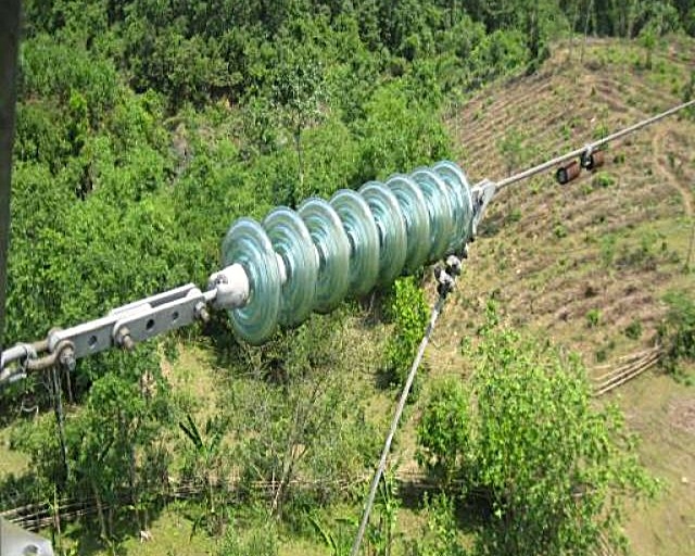
Suspension Insulators
Design and Mechanical Architecture
Suspension insulators represent the most sophisticated insulator type and are engineered for the most demanding electrical and mechanical applications. Rather than consisting of a single solid piece, suspension insulators comprise multiple individual glass discs or units stacked vertically and connected together by a central metal or composite core rod.
A typical suspension insulator string might include 10-50 individual glass units, depending on the voltage rating. Each disc measures approximately 250-300 millimeters in diameter and 100-150 millimeters in height, with specific geometric profiles optimized for high-voltage performance.
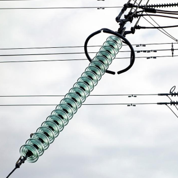
The modular construction of suspension insulators offers several critical advantages:
Voltage Flexibility: Each glass disc unit is rated for a specific voltage (typically 10-15 kV per disc). By stacking multiple units, engineers can create insulators for any required voltage by simply adding or removing units. For example, a 500 kV transmission line might require 40-50 stacked units, while a 345 kV line would require 25-30 units.
Replacement Efficiency: If a single disc becomes damaged or ages, the entire unit can be replaced without removing all connected discs. In pin insulators, any damage typically requires replacement of the complete insulator.
Mechanical Load Distribution: The stacked design distributes mechanical loads (tension from conductor weight, wind loading, ice accumulation) across multiple units, with each unit's mechanical capacity being leveraged.
Fault Detectability: If any single disc shatters, the gap becomes visible during inspection, signaling the need for replacement. This self-indicating failure mechanism is a critical safety advantage.
Applications in High-Voltage Transmission
Suspension insulators dominate high-voltage transmission systems, particularly in:
- Voltages exceeding 100 kilovolts
- Extra-high voltage (EHV) systems from 230 kV to 765 kV
- Ultra-high voltage (UHV) systems exceeding 1,000 kV
- Transmission lines subject to heavy mechanical loads (ice, wind)
- Areas with extreme pollution or coastal salt-spray exposure
The robust design and proven reliability of suspension insulators make them the standard choice for utilities seeking maximum operational security on critical transmission corridors.
Post Insulators
Configuration and Applications
Post insulators, alternatively termed "column insulators" or "busbar insulators," are vertical cylindrical structures mounted in substations and electrical equipment facilities. Unlike pin or suspension insulators designed for overhead line applications, post insulators support internal electrical equipment.
These insulators feature either cylindrical or square cross-sections, typically ranging from 500 millimeters to several meters in height depending on voltage and mechanical load requirements. Post insulators have flat or flanged mounting surfaces at both top and bottom for securing conductors, busbars, switches, or other equipment.
Specific Applications
Post insulators serve critical functions in:
- High-voltage substations (supporting busbars and switchgear)
- Circuit breaker and transformer installations
- Disconnect switches and grounding blade mechanisms
- Equipment in switchyards
- Indoor electrical installations requiring vertical insulation support
Design Considerations
Post insulators must accommodate both electrical insulation requirements and mechanical loading. A single post insulator might support loads of several thousand kilograms while maintaining electrical isolation across voltages exceeding 500 kV. The design must also prevent electrical tracking (surface electrical breakdown) through careful geometry that maximizes creepage distance.
Shackle Insulators
Form Factor and Function
Shackle insulators represent small, U-shaped glass components designed for specific low-voltage and distribution applications. These insulators typically measure 100-150 millimeters in width and 50-100 millimeters in height, weighing only 0.2-0.5 kilograms.
The U-shaped geometry accommodates a single conductor or cable that rests within the curved channel. Metal mounting hardware attached at each end of the U-shape permits installation on poles or structures.
Typical Applications
Shackle insulators are used in:
- Low-voltage distribution networks (below 15 kV)
- Temporary power installations
- Equipment connections where flexible positioning is required
- Grounding connections that must remain electrically isolated
- Cable support on poles where vibration isolation is beneficial
Advantages and Limitations
The compact size and low cost make shackle insulators economical for broad-based distribution applications. However, their relatively limited insulation capacity and mechanical strength restrict them to lower voltage applications. Shackle insulators represent excellent value in low-voltage systems but are inappropriate for transmission or industrial high-voltage applications.
Specialized Insulator Designs
Beyond these primary categories, manufacturers produce numerous specialized insulator designs engineered for specific applications:
Bell Insulators: Small, rounded dome-shaped insulators used historically for telephone and telegraph wires. The distinctive bell shape provided excellent water shedding in early telegraph systems.
Strain Insulators: Insulators specifically engineered to accommodate large mechanical tension loads where conductors make turns or branch points in transmission lines. These incorporate reinforced structures designed for ultimate tensile strengths exceeding 100 kiloNewtons.
Three-Piece or Ball-Socket Insulators: Designs featuring mechanical articulation or pivoting to accommodate differential movement between connected components while maintaining electrical isolation.
5.Electrical Properties and Performance Standards
Dielectric Strength: The Primary Electrical Characteristic
Dielectric strength represents the most critical electrical property of any insulator—the maximum electric field strength that the material can withstand without electrical breakdown and loss of insulating ability.
Definition and Measurement
Dielectric strength is defined as the voltage per unit thickness at which electrical breakdown occurs. The international standard unit is kilovolts per millimeter (kV/mm). For example, an insulator rated at 140 kV/cm (equivalent to 14 kV/mm) can theoretically withstand an electric field of 14,000 volts across a 1-millimeter air gap before breakdown occurs.
In practical terms, this property determines how thin an insulator can be designed while still maintaining a safety margin above the maximum operating voltage.
Glass Insulators vs. Alternative Materials
Glass electrical insulators demonstrate superior dielectric strength compared to competing materials:
- Glass insulators: 140 kV/cm
- Porcelain insulators: 60 kV/cm
- Polymer/Composite insulators: 15-30 kV/cm
This 2-3 times higher dielectric strength in glass compared to porcelain permits design of significantly lighter, more compact, and more cost-effective insulators while maintaining equivalent safety margins.
Factors Affecting Dielectric Strength
Numerous factors influence the actual dielectric strength experienced during field operation:
Humidity and Moisture: Moisture absorption reduces dielectric strength by creating conducting pathways along the insulator surface. Glass insulators, with their non-porous surface, resist moisture effects significantly better than porous ceramic materials. Extremely high humidity or wet conditions can reduce effective insulation by 10-30%.
Contamination and Surface Pollution: Salt deposits, industrial pollution, or dust accumulation on the insulator surface can reduce dielectric strength by creating conductive films that promote surface leakage currents. Glass's smooth surface resists contamination buildup more effectively than rough ceramic surfaces.
Temperature Effects: Elevated temperatures reduce the dielectric strength of most insulating materials by 0.5-1.0% per degree Celsius increase. Glass insulators demonstrate relatively good temperature stability compared to organic polymer insulators.
Electrical Stress Duration: Dielectric breakdown occurs more readily under prolonged electrical stress compared to brief high-voltage pulses. Standards distinguish between short-duration impulse strength (lightning strikes) and 60-cycle power frequency strength.
Mechanical Stress: Prior mechanical damage, particularly microscopic cracks invisible to naked inspection, dramatically reduces dielectric strength. Even hairline cracks can propagate under electrical stress, ultimately causing total dielectric failure.
Electrical Resistivity
Electrical resistivity measures the material's ability to resist electric current flow. Glass insulators exhibit extremely high resistivity—in the range of 10^11 to 10^12 ohm-centimeters—meaning that essentially no continuous current flows through the glass at normal operating voltages.
This extremely high resistivity is fundamental to the insulator function: while conductors like copper exhibit resistivity of approximately 0.000001 ohm-centimeters, insulator materials must exhibit resistivity many billions of times greater to effectively prevent current flow.
Dielectric Constant and Loss
The dielectric constant (or relative permittivity) of a material describes how readily the material polarizes when subjected to an electric field. Glass insulators exhibit a dielectric constant of approximately 6-8, meaning electric fields penetrate glass somewhat readily compared to vacuum (dielectric constant = 1.0) but far less readily than materials like water (dielectric constant = 80).
This intermediate dielectric constant is optimal for insulation applications, providing an appropriate balance between field intensity and material stress.
Dielectric loss—the energy dissipated as heat within the insulator material due to molecular friction during field cycling—remains extremely low in glass, typically less than 0.001% at power frequencies, whereas some ceramic materials exhibit losses exceeding 0.1%.
Insulation Resistance
Insulation resistance is typically measured by applying a DC test voltage for 1 minute and measuring the resulting current. Glass insulators typically demonstrate insulation resistances exceeding 10^14 ohms—a value so high that measurement requires specialized megohm meters. This extremely high resistance confirms the exceptional insulating capability of glass.
Performance Standards and Testing Protocols
International and national standards establish the testing protocols and acceptance criteria for electrical insulators:
IEC 60383 Series: The International Electrotechnical Commission's standards series specifying electrical insulator design, mechanical, and electrical testing requirements for porcelain and glass insulators.
IEEE 4: Standard high-voltage testing techniques establishing procedures for applying test voltages and measuring dielectric breakdown.
ASTM D149: American Society for Testing and Materials standard defining methods for dielectric breakdown voltage testing of solid electrical insulating materials.
These standards specify:
- Voltage rating procedures (how voltages are defined for different insulator types)
- Mechanical load testing protocols
- Electrical withstand testing (applying 50-65% of rated voltage or specified durations without failure)
- Thermal shock procedures (rapid temperature changes to verify annealing integrity)
- Pollution performance testing (salt fog, dust accumulation)
- Lightning impulse withstand testing
6.Advantages of Glass Insulators
Glass electrical insulators have emerged as the preferred choice for numerous high-voltage applications due to their distinctive performance advantages compared to competing materials. Understanding these advantages is essential for making informed procurement and design decisions.
1)Superior Dielectric Strength
Glass insulators deliver dielectric strength approximately 2.3 times greater than porcelain insulators—140 kV/cm versus 60 kV/cm. This superior electrical performance translates directly to:
- Reduced Required Thickness: For equivalent voltage ratings, glass insulators can be manufactured significantly thinner than porcelain alternatives, reducing weight by 20-40%.
- Increased Safety Margins: The excess dielectric strength provides substantial safety reserves against unexpected voltage surges, lightning strikes, or transient overvoltages.
- Simplified Design: Higher dielectric strength reduces the complexity of geometric design required to achieve creepage distance targets, permitting more compact, economical designs.
- Higher Operating Confidence: Engineers can specify glass insulators with complete confidence in electrical performance under severe electrical stress conditions.
2).Exceptional Tensile Strength
Glass insulators exhibit tensile strength of 35,000 kg/cm² compared to porcelain's 500 kg/cm²—a remarkable 70-fold advantage. This superior tensile strength means:
- Mechanical Reliability: Glass insulators can withstand extreme tension from heavy conductors, ice accumulation, wind loading, and sudden mechanical shocks without permanent deformation or failure.
- Lightweight Design: Because glass exhibits extraordinary strength per unit weight, insulators can be designed with minimal material, reducing installation loads and supporting structure requirements.
- Long Service Life: Superior tensile strength permits reliable performance even after decades of cumulative mechanical stress, thermal cycling, and environmental exposure.
3. Transparency and Fault Detection
Unlike opaque ceramic materials, glass insulators are transparent throughout their entire structure, enabling:
- Visual Internal Inspection: Quality control personnel and field inspectors can easily identify internal flaws, air bubbles, inclusions, or microcracking. Any significant internal defect appears as a visible discoloration, cloudiness, or shadow within the transparent glass.
- Self-Indicating Failure Mechanism: When glass insulators experience severe mechanical or electrical stress that exceeds material capability, they shatter completely and visibly—providing unmistakable indication that replacement is required. In sharp contrast, porcelain insulators can develop internal cracks or weakness that remains completely invisible until catastrophic failure occurs without warning.
- Reduced Maintenance Requirements: Because faults are immediately visible, utilities can identify and replace defective insulators during routine visual inspections, eliminating the need for specialized testing equipment or complex diagnostic procedures.
- Enhanced Safety: The transparent shattering mechanism prevents insidious failures where insulators gradually lose insulation capability while remaining physically intact, creating potential hazards.
4)Long-Term Electrical and Mechanical Property Stability
Unlike porcelain and many organic polymer materials, glass insulators do not experience age-related degradation of electrical or mechanical properties:
- Unchanging Performance: Research and field experience spanning over 150 years demonstrate that glass insulators in service since the 1800s still exhibit original electrical and mechanical properties without measurable degradation.
- No Aging Effects: Porcelain insulators frequently experience electrical property changes after 20-30 years of service due to microstructural changes and moisture penetration. Glass does not undergo such changes.
- Predictable Long-Term Reliability: Utilities can confidently operate glass insulators indefinitely (absent mechanical damage) without performance concerns, whereas porcelain installations typically require periodic testing and selective replacement after 25-30 years.
- Reduced Life-Cycle Costs: The extended service life without degradation eliminates the expensive periodic testing and replacement programs required for other materials.
5) Superior Pollution and Environmental Resistance
Glass insulators demonstrate exceptional performance in contaminated or corrosive environments:
- Salt-Spray Immunity: Coastal regions with high salt-spray exposure frequently experience premature failure of ceramic insulators due to surface salt film conducting leakage currents. Glass's smooth surface and superior hydrophobic properties resist salt accumulation, maintaining electrical performance indefinitely.
- Industrial Pollution Tolerance: In urban and industrial areas with air pollution, acid rain, or chemical vapor exposure, glass insulators consistently outperform ceramic alternatives. The chemically inert glass surface resists corrosion that would degrade ceramic surfaces.
- Dust and Particle Resistance: The smooth glass surface resists accumulation of atmospheric dust and particulate matter. Ceramic's rough, porous surface actively attracts and retains dust, which can create conducting pathways during high humidity or fog conditions.
- Self-Cleaning Properties: During rain events, water flows readily off smooth glass surfaces, carrying away accumulated contaminants. Ceramic surfaces retain moisture and dust in micro-surface irregularities.
- No Glaze Degradation: Some ceramic insulators rely on external glaze coatings for environmental protection. These glazes can crack, peel, or degrade over time, exposing underlying porous ceramic. Glass is uniform throughout, providing permanent protection.
6) Thermal Shock Resistance
Glass insulators withstand extreme and rapid temperature changes without cracking or degradation:
- Rapid Temperature Cycling: Heavy rain on a hot glass insulator causes sudden temperature reduction of 30-50°C. Glass insulators routinely tolerate such thermal shocks without cracking, whereas poorly annealed ceramic insulators may fail.
Sunlight Heating: Glass's transparency means solar radiation passes through the insulator, distributing heat evenly rather than creating the extreme surface heating that occurs on opaque ceramic. This reduces thermal stress and cracking risk.
- Winter/Summer Extremes: Glass maintains mechanical integrity through seasonal temperature swings ranging from -40°C to +60°C without performance degradation.
- Lightning-Induced Heating: The intense localized heating from lightning arc attachment causes rapid temperature spikes. Glass's excellent thermal conductivity distributes this heat rapidly, preventing localized melting or cracking.
7) Homogeneous Material Structure
Glass insulators are chemically and physically identical throughout their entire structure:
- No Internal Weakness Zones: Unlike porcelain, where external glaze differs from internal ceramic (creating potential delamination or internal fracture initiation sites), glass is structurally uniform throughout.
- Predictable Material Properties: Because the material is homogeneous, electrical and mechanical properties are reliably consistent regardless of where within the insulator a defect might initiate.
- Absence of Delamination: The absence of multiple material layers eliminates the possibility of surface layers separating from underlying material—a common failure mode in composite or layered insulators.
8)Light Weight and Compact Design
Glass insulators can be engineered to be substantially lighter than equivalent porcelain insulators:
- Reduced Installation Loads: Lighter insulators reduce mechanical stress on support structures, permitting use of lighter, less expensive poles and towers.
- Easier Handling and Installation: Field personnel can handle glass insulators with less specialized equipment and smaller crews, reducing installation labor costs and safety risks.
- Compact Footprint: The ability to design compact insulators permits more insulators to be mounted on existing structures without structural modifications.
- Transportation Efficiency: Lighter insulators require less fuel and smaller vehicles for transportation, reducing logistics costs and environmental impact.
9)Lower Cost Compared to Porcelain
Although manufacturing equipment and processes for glass insulators are sophisticated and capital-intensive, the finished insulators typically cost 15-30% less than equivalent porcelain units:
- Raw Material Economics: Glass manufacturing utilizes abundant, inexpensive silica sand, while ceramic insulators require specialized clays and more complex mineral processing.
- Manufacturing Efficiency: Glass forming processes (pressing and blowing) are faster and more automated than ceramic firing procedures, reducing labor costs.
- Reduced Quality Testing: The transparency of glass and self-indicating failure mechanism reduce the need for expensive electrical and mechanical testing, lowering production costs.
10) Excellent Mechanical and Electrical Stability at Extreme Temperatures
Glass insulators maintain consistent electrical and mechanical properties across an exceptionally broad temperature range:
- Cryogenic Performance: Glass insulators have been successfully deployed in arctic regions operating at temperatures reaching -50°C or lower without property degradation or brittleness.
- Tropical Heat Performance: In equatorial regions where ambient temperatures routinely exceed 45°C, glass insulators maintain original electrical properties without thermal stress cracking.
- Consistent Insulation: Unlike some organic polymers that soften or lose insulation at elevated temperatures, glass maintains rigid structure and excellent dielectric properties from -60°C to +90°C.
7.Disadvantages and Limitations
While glass electrical insulators offer numerous compelling advantages, they also present certain limitations and disadvantages that must be considered during material selection:
1)Brittleness and Impact Sensitivity
Glass remains fundamentally a brittle material, susceptible to fracture under mechanical impact:
Impact Vulnerability During Handling: Rough handling during transportation, storage, or installation can result in dropped insulators shattering upon impact with concrete or steel surfaces.
Mechanical Shock During Operation: Flying objects (tree branches, ice shards) or vandalism can shatter insulators. While porcelain insulators might develop hidden microcracks from similar impacts, glass insulators fail catastrophically and visibly.
Installation Risk: Installation crews must exercise careful handling procedures and provide protective cushioning during transportation and placement. This contrasts with robust porcelain insulators that tolerate rough handling better.
Mitigation Strategies: Modern installations employ protective packaging, specialized transportation containers, training in careful handling procedures, and field quality assurance inspections to minimize breakage rates.
2) Surface Moisture Condensation and Leakage Current Risk
Glass surfaces readily accumulate moisture through condensation, particularly in marine, tropical, or high-humidity environments:
Condensation Mechanism: When warm, humid air contacts cool glass surfaces—particularly during early morning hours or following rain—water condenses on the surface, creating a thin conductive film.
Leakage Current Initiation: This moisture layer, combined with atmospheric salt, dust, or pollutants, creates conductive pathways that permit leakage current to flow along the insulator surface. Excessive leakage current generates heat and can eventually lead to surface tracking—a carbonization process that permanently degrades insulation.
Performance in Marine Environments: In coastal regions with sea-salt spray, this limitation is particularly significant. Porcelain insulators' rough surfaces shed water more readily, while glass's smooth surface retains moisture longer.
Mitigation Approaches: Utilities mitigate this limitation through:
- RTV (room-temperature vulcanizing) silicone rubber coatings that enhance hydrophobicity and prevent moisture accumulation
- Regular washing and maintenance programs in high-pollution or marine areas
- Increased creepage distance (longer skirts) to extend the surface leakage path
- Selection of suspension insulators with optimized skirt geometry for water shedding
3) Design Inflexibility for Irregular Shapes
The inherent properties of glass constrain design possibilities for certain applications:
High-Voltage Shape Limitations: For extremely high voltages, achieving adequate creepage distance (the surface path length to prevent electrical tracking) requires increasingly complex, irregular geometric shapes. Glass cannot be cast into certain irregular, asymmetrical, or complex shapes economically due to internal thermal stress during annealing.
Porcelain Advantage: Ceramic materials can be shaped into nearly any form, permitting optimization of creepage distance through irregular skirt arrangements and optimized geometric profiles impossible with glass.
Design Consequences: This limitation restricts glass to voltages typically below 1,200 kV, while ceramic materials have been successfully deployed at higher voltages (1,500-1,200 kV) using optimized irregular geometries.
Practical Impact: For most practical applications (voltages below 765 kV), this limitation is insignificant, and glass's superior electrical properties at standard voltages more than compensate for this restriction.
4)Weight Limitations in Some Applications
Although glass insulators are generally lighter than equivalent porcelain insulators, practical applications can result in heavy suspension insulator strings:
Cumulative Weight: A suspension insulator string for 765 kV transmission might comprise 50-70 glass discs, creating a total weight of 50-100 kilograms suspended below a single transmission tower attachment point. This weight requires substantial mechanical capacity in the tower attachment hardware.
Installation Challenges: The weight of suspension insulator strings complicates installation procedures, requiring specialized rigging equipment and experienced personnel.
Tower Design Constraints: Heavy insulators can influence transmission tower design, sometimes requiring reinforced or heavier structural components.
Comparative Context: Despite these considerations, suspension insulator strings typically weigh 20-40% less than equivalent porcelain strings of the same voltage rating, representing a net advantage.
5)Complex Transportation and Handling Procedures
The brittleness of glass insulators necessitates more complex transportation and storage procedures:
Specialized Packaging: Insulators must be carefully wrapped, cushioned, and secured to prevent vibration and impact during transport. Specialized containers or pallets designed to minimize movement are required.
Handling Training: Installation and maintenance personnel require training in careful handling procedures that may be unnecessary with robust ceramic insulators.
Storage Limitations: Insulators must be stored under shelter to prevent impact and weather exposure. Extended outdoor storage is not acceptable as it might expose insulators to damage.
Transportation Cost Implications: The need for protective packaging and careful handling can increase transportation costs by 10-20% compared to ceramic alternatives.
6)Shorter Service Lifespan Compared to Ceramic Insulators
While glass insulators exhibit excellent long-term electrical property stability, their mechanical service lifespan may be somewhat shorter than ceramic alternatives:
Average Service Life: Glass insulators typically remain in reliable service for 50-100 years, while premium ceramic insulators may operate for 100-150 years.
Mechanical Degradation: Although electrical properties remain stable, subtle mechanical degradation can occur after decades of thermal cycling and mechanical stress, potentially reducing ultimate mechanical reliability in extreme situations.
Practical Implications: For most transmission systems, the 50-100 year service life of glass insulators substantially exceeds typical equipment maintenance cycles, making this limitation inconsequential.
8.Glass Insulators vs. Porcelain Insulators: Comprehensive Comparison
Both glass and porcelain insulators have been proven reliable through more than a century of service in electrical power systems. However, they exhibit significant differences in material properties, performance characteristics, cost, and optimal application environments. A detailed comparison provides guidance for material selection.
Electrical Performance Comparison
Characteristic | Glass Insulators | Porcelain Insulators | Advantage |
Dielectric Strength | 140 kV/cm | 60 kV/cm | Glass (2.3x higher) |
Electrical Resistivity | 10^11-10^12 Ω·cm | 10^10-10^11 Ω·cm | Glass |
Dielectric Constant | 6-8 | 6-10 | Comparable |
Dielectric Loss | <0.001% | 0.05-0.1% | Glass (lower loss) |
Humidity Sensitivity | Moderate | High | Glass (less affected) |
Analysis: Glass insulators demonstrate superior electrical properties across virtually all metrics. The significantly higher dielectric strength permits thinner, lighter insulator designs while maintaining superior safety margins. Lower dielectric loss translates to reduced heating during operation, particularly important for high-voltage systems carrying heavy loads.
Mechanical Properties Comparison
Property | Glass Insulators | Porcelain Insulators | Advantage |
Tensile Strength | 35,000 kg/cm² | 500 kg/cm² | Glass (70x higher) |
Compressive Strength | 10,000 kg/cm² | 70,000 kg/cm² | Porcelain (7x higher) |
Impact Resistance | Moderate | High | Porcelain |
Thermal Shock Resistance | Excellent | Good | Glass |
Mechanical Property Stability | Unchanging | Age-dependent | Glass |
Analysis: Glass and porcelain exhibit complementary strengths. Glass's superior tensile strength makes it ideal for tension-loaded applications (suspension insulators), while porcelain's compressive strength suits compression-loaded applications. However, glass's superior thermal shock resistance and unchanging mechanical properties provide long-term reliability advantages.
Environmental Performance Comparison
Environment | Glass | Porcelain | Superior Choice |
Salt-Spray (Coastal) | Excellent | Fair | Glass |
Industrial Pollution | Excellent | Fair | Glass |
Dust Accumulation | Low | High | Glass |
Moisture Condensation | Moderate | Low | Porcelain |
UV Radiation | Excellent | Excellent | Comparable |
Temperature Extremes | Excellent | Good | Glass |
Analysis: Glass insulators excel in salt-spray and pollution environments, while porcelain performs better in extremely humid environments. For most environments, glass's superior pollution resistance compensates for its slightly higher moisture condensation tendency.
Fault Detection and Maintenance
Aspect | Glass | Porcelain | Advantage |
Visual Defect Detection | Excellent (Transparent) | Poor | Glass |
Self-Indicating Failure | Yes (Visible Shattering) | No (Hidden Cracking) | Glass |
Testing Requirements | Minimal | Extensive | Glass |
Maintenance Labor | Low | High | Glass |
Inspection Complexity | Simple Visual | Specialized Tools | Glass |
Analysis: Glass insulators' transparency and self-indicating failure mechanism provide significant maintenance advantages, reducing the need for costly specialized testing equipment and procedures. A utility inspector can immediately identify failed glass insulators during routine line inspections, whereas porcelain defects require diagnostic testing.
Cost Analysis
Factor | Glass | Porcelain | Cheaper |
Material Cost | $500-$2,000 | $400-$1,500 | Porcelain (slightly) |
Manufacturing Cost | $300-$1,200 | $400-$1,500 | Glass |
Testing Cost | $50-$200 | $200-$500 | Glass |
Installation Cost | $200-$600 | $200-$600 | Comparable |
Maintenance Cost (20 years) | $1,000-$3,000 | $5,000-$15,000 | Glass |
Total Life-Cycle Cost | $2,000-$7,000 | $5,000-$20,000 | Glass (typically 30-40% lower) |
Analysis: While the initial material and manufacturing cost of glass and porcelain insulators are relatively comparable, glass insulators deliver significant life-cycle cost advantages through reduced maintenance requirements, minimal testing needs, and longer practical service life without performance degradation.
Application Recommendations
Optimal Glass Insulator Applications:
- High-voltage transmission systems (>100 kV)
- Coastal or marine environments with salt spray
- Industrial areas with significant air pollution
- Applications requiring minimal maintenance
- Systems where visible fault detection is valuable
- Areas with temperature extremes or thermal cycling challenges
Optimal Porcelain Insulator Applications:
- Lower-voltage distribution systems (<35 kV)
- Humid tropical environments with extensive condensation
- Applications where mechanical ruggedness is paramount
- Historical or aesthetic considerations
- Regions with established porcelain infrastructure and expertise
Comparative Advantage Summary:
Glass insulators now dominate high-voltage transmission applications worldwide, with utilities in the United States, Canada, Russia, Sweden, United Kingdom, and Australia preferring glass for new installations. Porcelain remains widely used in Asia and Africa, where traditional manufacturing expertise and established supply chains favor ceramic materials.
9.Applications in Modern Power Systems
Glass electrical insulators serve critical functions across diverse applications within electrical power generation, transmission, distribution, and industrial power systems.
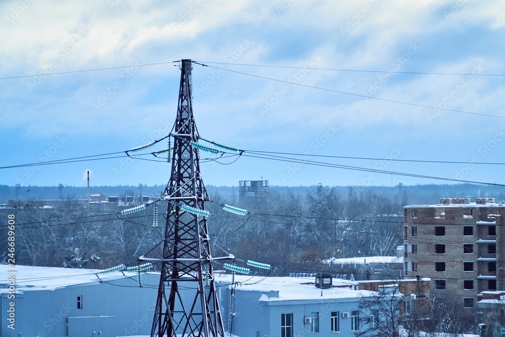
High-Voltage Transmission Lines (≥230 kV)
Suspension insulators comprising stacked glass discs represent the predominant insulator type on modern transmission lines operating at voltages of 230 kV to 765 kV, with experimental systems reaching 1,200 kV.
Mechanical Function: Transmission line insulators must support enormous tension loads as conductors weighing 1,000+ kilograms per span are suspended beneath transmission towers. Suspension insulator strings, often comprising 20-50 individual glass discs, collectively withstand tensions exceeding 50,000 kilograms while maintaining electrical isolation.
Environmental Challenges: Transmission lines operate continuously in exposed environments subject to:
- Ice accumulation of 50+ millimeters thickness, creating mechanical loads exceeding normal conductor weight
- Wind speeds reaching hurricane force (>200 km/h), inducing dynamic vibration and mechanical stress
- Salt spray and airborne contamination in coastal regions
- Temperature variations from -40°C to +60°C
- Lightning strikes carrying currents exceeding 200,000 amperes
Glass insulators' combination of superior mechanical strength, environmental resistance, and transparent fault detection makes them ideal for these demanding applications.
Maintenance Advantages: Utilities operating transmission lines employ visual inspection protocols where line crews conduct periodic inspections (every 2-5 years) along entire transmission corridors. Any shattered glass insulators become immediately visible during these inspections, permitting targeted replacement of failed units. In contrast, porcelain insulators might develop internal cracks that remain invisible until catastrophic failure occurs without warning.
Distribution Systems (10-69 kV)
Distribution systems operating at medium voltages employ pin-type glass insulators to support conductors on wooden poles throughout urban, suburban, and rural areas. Individual pin insulators typically measure 100-200 millimeters in height and are rated for specific voltages (5 kV, 10 kV, 15 kV, 25 kV, 35 kV, etc.).
Practical Considerations: Distribution networks demand cost-effective insulators that require minimal maintenance. The transparency of glass insulators allows distribution maintenance crews to identify failed insulators during routine pole inspection activities, eliminating the need for specialized testing equipment.
Environmental Resilience: Distribution systems in coastal regions benefit greatly from glass insulators' superior salt-spray resistance. Utilities in California, Florida, and other coastal states have observed significantly longer service life from glass insulators compared to ceramic alternatives in identical environmental conditions.
Substation Equipment Support
Post insulators constructed from glass are increasingly employed in substations to support high-voltage busbars, switches, disconnects, and other equipment. These vertical insulators must accommodate both electrical insulation requirements and mechanical support loads.
Space Efficiency: Substations typically operate in space-constrained environments where minimal space is available for insulation structures. Glass insulators' high mechanical and electrical strength permit compact designs that minimize space requirements while maintaining required insulation margins.
Maintenance Access: The transparent nature of glass insulators permits visual inspection for contamination, moisture accumulation, or damage from within the substation environment, allowing identification of maintenance needs without specialized tools or procedures.
Industrial Power Systems
Large industrial facilities (steel mills, petrochemical plants, pulp/paper mills) employ glass insulators in their internal distribution systems, switchyards, and equipment connections. Industrial environments frequently feature extreme temperatures, aggressive chemical vapors, dust, and vibration—conditions where glass insulators' environmental resistance provides significant advantages.
Coastal and Marine Applications
Offshore wind farms, coastal generation facilities, and marine electrical installations increasingly employ glass insulators due to their exceptional salt-spray immunity. Unlike ceramic insulators that require expensive protective coatings (hydrophobic RTV silicone rubber) or aggressive maintenance cleaning regimens in marine environments, glass insulators maintain performance indefinitely without special treatment.
Extreme Environment Applications
Glass insulators have been successfully deployed in:
Arctic Regions: Electrical systems in Alaska, Russia, and northern Canada operate glass insulators at temperatures reaching -50°C. Glass maintains mechanical integrity and electrical properties at cryogenic temperatures where some materials become brittle or lose insulation.
Tropical Regions: Equatorial installations with ambient temperatures exceeding 50°C and extreme humidity operate glass insulators successfully. The superior thermal stability and moisture condensation resistance of glass provide reliable performance in these challenging environments.
High-Altitude Installations: At altitudes exceeding 3,000 meters, atmospheric pressure reduction affects electrical performance. Glass insulators' superior dielectric strength provides additional safety margins in thin-air environments where electrical breakdown risks increase.
Specialized Applications
Lightning Protection: The superior thermal shock resistance of glass insulators makes them particularly suitable for systems in lightning-prone regions. During lightning attachment, the extremely high currents (50,000-200,000 amperes) and elevated temperatures (30,000+ K) subject insulators to severe thermal shock. Glass's excellent thermal conductivity and shock resistance prevent cracking.
Seismic Areas: Earthquake-prone regions of Japan, California, and elsewhere employ glass insulators in critical systems where mechanical reliability is paramount. The high tensile strength of glass insulators permits reliable performance during seismic events where transmission tower movement induces dynamic mechanical stress.
High-Frequency Applications: Certain power conditioning and specialized industrial applications employ glass insulators for their superior dielectric properties and low dielectric loss at elevated frequencies (multiple kilohertz).
10.Installation, Maintenance, and Safety Considerations
Installation Procedures
Pre-Installation Inspection
Before installation, all glass insulators require careful visual inspection:
- Examine for cracks, chips, or surface damage that would compromise performance
- Verify dimensional conformance (pin hole threading, overall height/diameter)
- Check that the pin hole threads are clean and undamaged
- Document serial numbers or other identification information for future reference
Protective Handling
- Never drop insulators or permit them to contact hard surfaces
- Provide protective wrapping or cushioning during transportation
- Avoid contact between insulators (glass-to-glass contact can cause damage)
- Store in covered environments protected from weather and impact
Mechanical Attachment
- Attach insulators to properly dimensioned support pins (wooden, composite, or metal per design specifications)
- Ensure pin hole threading engages fully to prevent axial movement
- Apply threadlocker compounds (per specification) to prevent vibration-induced loosening
- Verify secure attachment before applying electrical load
Electrical Connection
- For pin insulators: Attach conductors to the ceramic dome using appropriate binding materials or attachment hardware
- For suspension insulators: Attach conductors to the terminal hardware at the lower extremity of the insulator string
- Ensure electrical connections are mechanically secure and permit appropriate thermal expansion
Maintenance Programs
Visual Inspection Schedule
Transmission line insulators: Routine visual inspection every 2-3 years by helicopter, drone, or climbing crews
Distribution line insulators: Visual inspection during annual pole inspection cycles
Substation insulators: Quarterly visual inspection during routine substation maintenance activities
Inspection Procedures
- Photograph all visible defects for documentation and trending
- Identify cracked, chipped, or missing insulators requiring replacement
- Note accumulation of salt, dust, or contamination requiring cleaning
- Document any electrical tracking (carbonization) or surface damage
- Record environmental conditions (humidity, temperature, precipitation) during inspection
Cleaning and Maintenance
- In marine or industrial pollution environments, periodic cleaning with deionized water improves insulation performance
- Remove accumulated salt, dust, or conductive contamination
- High-pressure washing can be effective but must use deionized water (tap water leaves mineral deposits)
- Some utilities apply hydrophobic RTV silicone rubber coatings in extreme marine environments to enhance water shedding
Replacement Procedures
- For pin insulators: Remove the conductor, unbolt the insulator from the pole hardware, install the replacement unit, and reconnect the conductor
- For suspension insulators: The failed disc is typically replaced by removing the hardware connecting it to adjacent discs, removing the failed unit, and installing the replacement. Individual disc replacement is often faster than re-stringing the entire insulator suspension
Testing and Diagnostics
Unlike porcelain insulators that require periodic electrical testing to identify hidden internal defects, glass insulators typically require minimal diagnostic testing:
- Visual inspection suffices to identify failed glass insulators (which shatter visibly)
- High-voltage testing is performed during manufacturing but rarely required in-service
- If electrical testing is performed, DC megohm meters can verify insulation resistance (should exceed 10^14 ohms)
Safety Considerations
Personnel Safety During Installation and Maintenance
- Glass insulators remain potential electrical conductors despite their insulating function—never work on energized circuits without proper de-energization and grounding procedures
- Always de-energize transmission lines before beginning any work on insulators
- Use appropriate personal protective equipment (PPE) including insulating gloves, hard hats, and safety harnesses for elevated work
- Train personnel in careful handling procedures to minimize breakage and injury risk from dropped insulators High-Voltage Arc Safety
- During emergency replacement of failed insulators, proper grounding and arc flash procedures must be followed
- The sharp edges of freshly broken glass insulators can present cut hazards; appropriate hand protection is required
Environmental and Disposal Considerations
- Broken glass insulators must be carefully collected and disposed of as glass waste
- Insulators can be recycled as common glass; they contain no hazardous materials or asbestos (some older insulators may contain trace amounts of lead oxide as a flux—proper disposal procedures are recommended for insulators manufactured before 1980)
- Recycled glass insulators can be reused in glassmaking, glass fiber production, or other applications
11.Historical Development and Evolution
The Telegraph Era (1840s-1860s)
Glass insulators first appeared in the 1840s as telegraph technology was expanding across North America and Europe. Early telegraph lines required insulators to prevent electrical signals from grounding out on wooden poles, and engineers rapidly recognized glass's superior electrical properties compared to ceramic alternatives.
Early Designs: Initial telegraph insulators were remarkably simple—short, thick glass cylinders with minimal geometric refinement. These early designs, manufactured by companies like Hemingray and Brookfield, established many characteristics that persist in modern insulators: the dome at the upper extremity, internal threads for pin attachment, and external ridges or skirts for water shedding.
Manufacturing Challenges: Early glass insulator production faced significant challenges. Annealing processes were not fully understood, resulting in high breakage rates from thermal shock and mechanical stress. Many glass insulators from the 1860s and 1870s cracked or shattered during initial service.
The Telephone Era (1870s-1920s)
As Alexander Graham Bell's telephone technology spread rapidly in the late 19th century, demand for telephone insulators exploded. The telegraph industry had evolved into a mature market with established technology, while telephone expansion created massive demand for new insulators and manufacturing capacity.
Expanded Manufacturing: Dozens of glass manufacturers entered the insulator business during this period. Companies like Whitall Tatum, McLaughlin, and others established major glass insulator manufacturing facilities. By 1900, thousands of different glass insulator designs and styles existed, differentiated by manufacturer, vintage, color, and embossing details.
Technological Refinement: Improved annealing procedures dramatically reduced cracking rates. By 1910, glass insulator quality and reliability had improved substantially compared to earlier products.
Color Variation: As manufacturing capacity expanded and competition intensified, manufacturers began producing insulators in varied colors—aqua, clear, green, amber, and blue. These color variations resulted from subtle differences in raw material composition and manufacturing conditions.
The Power Distribution Era (1920s-1960s)
As electrical power systems expanded dramatically in the early-to-mid 20th century, glass insulators transitioned from predominantly telecommunications use to power system applications. Larger suspension insulators were developed for transmission lines, while smaller pin-type insulators proliferated in distribution networks.
Peak Production: The 1930s-1950s represented peak glass insulator production volumes. Millions of insulators were manufactured annually to support expansion of power grids across North America, Europe, and industrial nations worldwide. During this period, glass insulators dominated the market, as porcelain alternatives were still being perfected.
Standardization: International standards emerged during this period, defining insulator specifications, testing procedures, and performance requirements.
The Modern Era (1960s-Present)
Beginning in the 1960s, alternative insulator materials emerged, challenging glass's market dominance:
Porcelain Renaissance: Porcelain insulator manufacturing was significantly improved during the 1960s-1980s. Modern porcelain processes, superior glazes, and refined designs made porcelain more competitive with glass. Porcelain's longer service life and superior mechanical robustness appealed to utilities seeking economical long-term solutions.
Polymer Composites: Beginning in the 1980s-1990s, polymer composite insulators (fiberglass-reinforced plastic) emerged as a third material option. These lightweight, corrosion-resistant materials offered advantages in specific applications, though their long-term electrical performance remains less proven than glass or ceramic.
Regional Preferences: Despite competition, glass maintained dominance in North America, Northern Europe, and certain other regions where superior electrical performance and minimal maintenance were valued. Porcelain remained predominant in Asia and Africa where manufacturing expertise and cost considerations favored ceramic materials.
Technological Improvements: Modern glass insulators incorporate improved annealing procedures, refined glass formulations, and optimized geometric designs based on computer modeling and field experience. Contemporary glass insulators achieve higher reliability and consistency than vintage products.
Collector Market and Vintage Insulators
Parallel to professional electrical use, a substantial enthusiast collector market for vintage insulators developed in the 1970s-1980s. Collectors appreciate vintage insulators for their historical significance, aesthetic qualities, manufacturing variety, and nostalgic value. This collector market remains active today, with organized clubs, auctions, and specialized price guides.
Collector Designations: The National Insulator Association (NIA) developed a standardized CD (Consolidated Design) numbering system for identifying and cataloging different glass insulator styles. CD numbers permit precise identification of insulator type, manufacturer, vintage, and production era.
Value Factors: Collector values depend on multiple factors:
- Rarity of the specific design and manufacturer
- Color (certain colors are rarer than others)
- Condition (perfect condition commands premium prices)
- Embossing details
- Age and historical significance
Some rare antique insulators, particularly from manufacturers like EC&M Co. (associated with the Transcontinental Telegraph), command prices ranging from $500 to $5,000+, while common everyday insulators might sell for $1-$10.
Important Distinction: The collector market for vintage insulators is entirely separate from industrial electrical specifications. Antique collection insulators cannot be used for new electrical installations—such application would be unsafe and inappropriate. Modern high-voltage applications require insulators manufactured to contemporary electrical standards (IEC, IEEE, ASTM) that ensure electrical performance, mechanical integrity, and safety.
12.Frequently Asked Questions (FAQ)
1)Is Glass a Conductor or Insulator of Electricity?
Answer: Glass is an excellent electrical insulator. It exhibits extremely high electrical resistivity (10^11-10^12 ohm-centimeters), meaning it resists electrical current flow millions of billions of times better than conductors like copper. The primary function of glass electrical insulators is to prevent unwanted current flow by providing a high-resistance barrier. The insulating properties remain virtually unchanged for centuries, making glass one of the most reliable insulating materials known.
2)What Are the Main Uses of Glass Insulators?
Answer: Glass electrical insulators serve three primary functions:
- Electrical Insulation: Preventing electrical current from flowing from live conductors to grounded structures, poles, or equipment
- Mechanical Support: Supporting the weight of electrical conductors while maintaining electrical isolation
- Environmental Protection: Protecting conductors and connections from weather, contamination, and physical damage
Specific applications include:
- High-voltage transmission lines (230-765 kV)
- Distribution networks (10-69 kV)
- Substation equipment support
- Industrial power systems
- Telecommunications installations (historical)
3)What Is Glass Insulator Identification and How Is It Performed?
Answer: Glass insulator identification involves determining the insulator's type, manufacturer, vintage, and characteristics. Identification methods include:
Visual Characteristics:
- Embossing: Manufacturer names and dates embossed on the glass surface
- Shape and Size: Distinct profile shapes varied by manufacturer and vintage
- Color: Dominant color (aqua, clear, green, blue, amber, purple) reflects manufacturing era
- Dome Profile: Shape of the upper dome section
- Skirt Configuration: Number and profile of ridges or external projections
CD Number Classification: The standardized CD (Consolidated Design) numbering system permits precise identification of specific insulator designs. CD numbers incorporate manufacturer information, voltage rating, and design characteristics.
Professional References: Publications like "Insulators: A History and Guide to North American Glass Pintype Insulators" by John and Carol McDougald provide comprehensive identification information, while the National Insulator Association (NIA) maintains extensive databases of known designs.
4)What Is the Difference Between High-Voltage Porcelain Insulators and Glass Insulators?
Answer: Key differences include:
Characteristic | Glass | Porcelain |
Dielectric Strength | 140 kV/cm | 60 kV/cm |
Tensile Strength | 35,000 kg/cm² | 500 kg/cm² |
Transparency | Yes (visible defects) | No (hidden defects possible) |
Environmental Resistance | Excellent in salt/pollution | Good but requires maintenance |
Aging Effect | None (unchanging properties) | Properties degrade over 20-30 years |
Service Life | 50-100+ years | 50-150 years |
Maintenance | Minimal (visual inspection) | Periodic testing required |
Cost | Lower life-cycle cost | Higher long-term cost |
Glass insulators are generally preferred for high-voltage transmission due to superior electrical properties and minimal maintenance requirements.
5)How Are Glass Electrical Insulators Manufactured?
Answer: The manufacturing process involves eight main stages:
- Raw Material Selection: Silica sand, soda ash, limestone, and additives are carefully proportioned
- Material Mixing: Raw materials are combined in industrial mixers
- Furnace Melting: Materials are heated to 1,400-1,600°C with continuous stirring to eliminate bubbles
- Forming: Molten glass is pressed or blown into molds to create the insulator shape
- Annealing: The formed insulator undergoes controlled heating and slow cooling to relieve internal stresses
- Cooling: The insulator cools to room temperature under controlled conditions
- Quality Inspection: Visual, dimensional, and electrical testing verify conformance to specifications
- Packaging and Shipping: Insulators are carefully packaged for transportation
This process typically requires 48-96 hours from raw material to finished product.
6)What Maintenance Do Glass Insulators Require?
Answer: Glass insulators require minimal maintenance compared to ceramic alternatives:
- Routine Inspection: Visual inspections every 2-5 years identify shattered or obviously damaged insulators
- Contamination Cleaning: In marine or highly polluted environments, periodic washing with deionized water removes salt and dust buildup
- Replacement: Failed insulators (identifiable by visible shattering) are replaced with new units
- Testing: High-voltage testing is typically not required in-service, unlike porcelain insulators
The transparent nature of glass makes maintenance schedules significantly simpler than those for opaque ceramic materials, reducing overall system operating costs.
13.Conclusion and Future Outlook
Summary of Key Points
Glass electrical insulators represent a mature, proven technology with over 180 years of demonstrated reliability in electrical power systems worldwide. These engineered components combine superior electrical properties, exceptional mechanical strength, environmental resistance, and transparent fault detection capability in a cost-effective package.
The fundamental advantages of glass insulators remain compelling:
- Superior Dielectric Strength: Approximately 2.3 times higher than porcelain alternatives, permitting compact, lightweight designs
- Exceptional Tensile Strength: 70 times greater than porcelain, enabling reliable performance under extreme mechanical loads
- Transparent Fault Detection: Visual identification of internal defects and self-indicating failure mechanism through visible shattering
- Property Stability: Electrical and mechanical properties remain unchanged for decades or centuries, eliminating age-related degradation
- Environmental Resilience: Superior performance in salt-spray, pollution, and extreme temperature environments
- Minimal Maintenance: Transparent design and self-indicating failures reduce maintenance requirements and costs
- Life-Cycle Economics: Typically 30-40% lower total cost of ownership compared to ceramic alternatives
Current Market Status
Glass insulators remain the predominant choice for high-voltage transmission systems globally. Utilities in North America, Northern Europe (United Kingdom, Sweden, Russia), Canada, and Australia continue to specify glass insulators for new installations and major equipment replacements.
This preference reflects:
- Proven performance over multiple generations of equipment
- Superior electrical properties supporting increasingly demanding transmission requirements
- Minimal operational and maintenance costs
- Compatibility with modern power system automation and monitoring
Porcelain insulators retain market share in Asia and Africa, where manufacturing traditions, regional cost considerations, and established supply chains support ceramic materials. Polymer composite insulators capture certain specialty applications, particularly where lightweight designs are paramount.
Emerging Technologies and Future Developments
Nanotechnology and Advanced Materials: Research is exploring nanostructured glass with enhanced properties, including improved resistance to moisture condensation and superior mechanical strength. These developments may further extend the performance advantages of glass insulators.
Smart Insulators: Integration of sensors into insulator structures to monitor electrical performance, mechanical stress, temperature, and contamination levels promises enhanced diagnostics and predictive maintenance capabilities.
Hybrid Designs: Some manufacturers are exploring hybrid insulator designs combining glass mechanical elements with advanced polymeric or composite surfaces optimized for specific environmental challenges.
Environmental Sustainability: Glass insulators' full recyclability and minimal environmental impact during manufacturing position them favorably as utilities increasingly prioritize sustainable practices. Recycled glass content in manufacturing continues to increase.
Industry Standards and Regulation
International standards (IEC 60383 series, IEEE 4, ASTM D149) continue to evolve, incorporating field experience and advanced materials science. These standards ensure that glass insulators manufactured worldwide meet consistent performance criteria regardless of origin.
Strategic Recommendations for Industry Professionals
For Utility Engineers and Procurement Specialists:
- Specify glass insulators for high-voltage transmission and distribution applications (≥100 kV) where superior electrical properties and minimal maintenance align with system requirements
- Conduct life-cycle cost analyses comparing glass, porcelain, and composite alternatives—the superior long-term economics of glass typically justify specified selection
- Implement visual inspection protocols appropriate to glass insulators' transparent design, eliminating unnecessary specialized testing
- Establish preventive maintenance programs emphasizing periodic visual inspection and contamination management
For Manufacturing and Supply Chain Professionals:
- Engage with manufacturers certified to international standards(IEC 60383, IEEE, ASTM) ensuring product consistency and performance
- Implement quality assurance procedures verifying electrical properties through testing representative production samples
- Establish supplier relationships with manufacturers demonstrating consistent delivery, quality control, and technical support
For Researchers and Technology Developers:
- Investigate advanced glass formulations with enhanced specific properties (improved pollution resistance, superior thermal shock tolerance)
- Develop integrated sensor and monitoring technologies for smart insulator applications
- Explore manufacturing innovations reducing production costs and environmental impact
- Conduct long-term field studies of glass insulators in extreme environments to validate performance predictions and identify improvement opportunities
Final Perspective
Glass electrical insulators represent a crystallized example of successful materials science and engineering—a technology refined over nearly two centuries to achieve exceptional performance across demanding applications. Their combination of superior electrical properties, mechanical strength, environmental resistance, and transparent design provides optimal characteristics for modern electrical power systems.
As electrical grids evolve to accommodate renewable energy integration, HVDC transmission expansion, and enhanced automation, glass insulators continue to demonstrate the performance, reliability, and longevity that sophisticated electrical systems demand. Their proven track record, combined with ongoing technological refinement and enhanced manufacturing processes, positions glass insulators as the material of choice for critical electrical infrastructure well into the future.
The transparency of glass insulators—both literal optical transparency and figurative transparency of performance and reliability—makes them an exemplary choice for electrical systems where visible certainty and proven dependability are paramount.