
Electrical Glass Insulator Selection for Kenya’s 132kV KPLC Substation Project
A Comprehensive Guide to High-Voltage Insulator Solutions for Industrial, Urban, and Rural Substation Infrastructure
")
Introduction: Kenya’s Power Landscape and the 132kV KPLC Substation Project
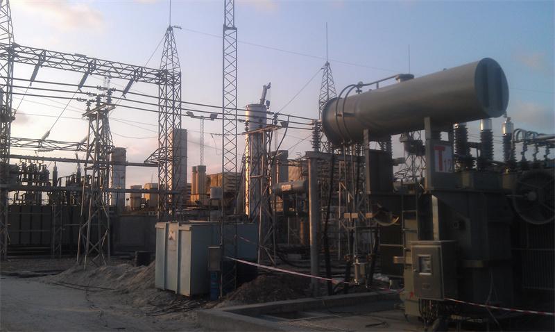
Kenya, East Africa’s economic powerhouse, is experiencing rapid urbanization, industrial growth, and rural electrification—driving an urgent need to upgrade its power infrastructure to meet rising energy demand. At the center of this transformation is the Kenya Power and Lighting Company (KPLC), the country’s principal electricity distributor, tasked with delivering reliable power to over 10 million customers across urban centers, industrial zones, and remote rural communities. The 132kV KPLC Substation Project—launched in phases between 2021 and 2024—represents a critical investment in modernizing Kenya’s power grid: it involves the construction and upgrade of 18 key substations across the country, connecting high-voltage transmission lines (132kV) to medium-voltage distribution networks (33kV/11kV) and serving as critical hubs for power transfer between generation facilities (e.g., geothermal plants in the Rift Valley, hydroelectric stations along the Tana River) and end users.
These 132kV substations are strategically located to address Kenya’s most pressing energy challenges: mitigating frequent power blackouts caused by aging infrastructure, improving voltage stability for industrial users (e.g., manufacturing plants, mining operations), and expanding access to reliable power in underserved rural areas. Unlike transmission lines, which are exposed to open-air conditions, substations house critical equipment—including transformers, circuit breakers, busbars, and switchgear—requiring insulators that not only provide superior electrical insulation but also withstand mechanical loads, resist environmental contamination, and integrate seamlessly with existing hardware. The 132kV KPLC Substation Project is not just a technical upgrade; it is a cornerstone of Kenya’s efforts to reduce power outages, lower technical losses, and support sustainable economic growth.
At the heart of this project lies a critical technical decision: selecting the right electrical tempered glass insulators to ensure decades of safe, uninterrupted operation. Kenya’s unique environmental conditions—including industrial pollution in urban centers, agricultural dust in rural areas, coastal salt fog in Mombasa and other coastal regions, and high-altitude conditions in the Rift Valley—combined with the high electrical stresses of 132kV systems, demand a context-driven insulator selection process. This article breaks down the step-by-step selection process tailored explicitly to Kenya’s 132kV KPLC Substation Project, explaining how every choice aligns with the substations’ working conditions, IEC international standards, KPLC’s operational requirements, and Kenya’s long-term energy goals.
1. Step One: Voltage Level as the Cornerstone of Insulator Selection for 132kV Substations
The first and non-negotiable criterion in insulator selection for any power project is the system’s voltage level. For Kenya’s 132kV KPLC Substation Project, the substations operate at a nominal maximum voltage of 145kV (the standard for 132kV grids globally, as defined by IEC 60273), which demands insulators that can withstand far higher electrical stresses than low- or medium-voltage applications. Unlike transmission lines, which use insulator strings to distribute electrical stress, substation insulators (primarily post-type) must provide standalone insulation and support for busbars, circuit breakers, and other equipment—making their voltage rating even more critical.
Why 132kV (145kV) Requires Specialized Substation Insulator Design
132kV substations occupy a critical position in Kenya’s power grid, acting as the “bridge” between high-voltage transmission (220kV/400kV) and medium-voltage distribution (33kV/11kV). This role demands insulators that meet two core electrical performance goals, aligned with KPLC’s strict operational standards and IEC 60168 (the international standard for station post insulators):
1. Withstand Transient Overvoltages: Substations are vulnerable to transient overvoltages from lightning strikes, switching operations, and grid faults—events that can generate voltages 3–5 times the nominal 145kV. To prevent flashover (the sudden breakdown of insulation that causes power outages and equipment damage), IEC 60168 and KPLC’s technical specifications mandate the following minimum withstand voltage ratings for 132kV substation insulators:
○ Power Frequency Withstand Voltage: 275 kV rms (1-minute test) – this ensures the insulator can withstand sustained high voltages during grid faults or switching operations.
○ Lightning Impulse Withstand Voltage: 650 kV peak (1.2/50μs wave) – critical for protecting substation equipment from lightning-induced surges, which are common in Kenya’s tropical climate.
○ Switching Impulse Withstand Voltage: 550 kV peak (250/2500μs wave) – designed to resist overvoltages caused by the switching of high-voltage circuit breakers, a frequent operation in substations.
2. Insulation for Busbar and Equipment Support: Substation insulators (primarily post-type) must provide reliable insulation between live busbars and grounded substation structures (e.g., steel frames, concrete foundations). Unlike transmission line insulators, which hang conductors, substation post insulators are mounted vertically or horizontally to support busbars and equipment—requiring a solid, rigid design that maintains insulation integrity even under mechanical stress. For 132kV substations, this means insulators with a minimum insulation height of 1500mm (as specified in Northern Powergrid’s technical standards for 132kV post insulators) to ensure adequate clearance between live parts and ground.
Comparing 132kV Substation Insulator Requirements to Other Voltage Levels in Kenya
To highlight the uniqueness of 132kV substation insulator selection, it is critical to contrast it with other voltage classes in Kenya’s power grid—especially since KPLC’s substations handle multiple voltage levels (132kV, 33kV, 11kV) in a single facility:
• 11kV/33kV Distribution Substations: These lower-voltage substations require insulators with a power frequency withstand voltage of 35–95 kV rms and a lightning impulse withstand voltage of 95–200 kV peak. They use smaller, lighter post insulators (minimum length 445–770mm) that are not designed to handle the high electrical stresses of 132kV systems. Using 33kV insulators in a 132kV substation would result in immediate flashover and equipment failure.
• 220kV/400kV Transmission Substations: These ultra-high-voltage substations demand insulators with a power frequency withstand voltage of 395 kV rms and a lightning impulse withstand voltage of 1050 kV peak—far exceeding the requirements of 132kV substations. Using 220kV insulators in a 132kV substation would be unnecessarily costly (increasing material costs by 40–50%) without providing any additional performance benefits.
This balance makes 132kV-specific tempered glass post insulators the only viable choice for KPLC’s 132kV substations. They meet the exact electrical demands of the 145kV nominal maximum voltage while avoiding overengineering—critical for KPLC, which faces financial constraints and must optimize costs without compromising reliability.
Additionally, KPLC’s 132kV substations must comply with the company’s efforts to modernize its infrastructure and reduce power outages. The selected insulators must integrate with KPLC’s upgraded SCADA/EMS (Supervisory Control and Data Acquisition/Energy Management System), which monitors grid performance and enables faster fault detection—making reliable insulation a key component of the system’s overall efficiency.
2. Step Two: Mechanical Load Assessment – Matching Insulator Strength to Kenya’s Substation Conditions
While electrical performance is critical, substation insulators are also load-bearing components that must withstand mechanical forces—including the weight of busbars, wind loads, equipment vibration, and thermal expansion/contraction. For Kenya’s 132kV KPLC Substations, these mechanical loads vary depending on the substation’s location (urban vs. rural, coastal vs. high-altitude) and the type of equipment being supported. Unlike transmission line insulators, which primarily resist tensile loads (conductor tension), substation post insulators must resist cantilever loads (bending forces from busbars and wind) and compressive loads (weight of equipment), making their mechanical design uniquely challenging.
Key Mechanical Loads for 132kV Substation Insulators
Kenya’s 132kV KPLC Substations face four primary mechanical loads, each requiring careful consideration during insulator selection:
1. Busbar Weight and Tension: 132kV substations use rigid busbars (typically aluminum or copper) that can weigh up to 120kg per meter (including connectors and hardware). Post insulators must support this weight without bending or breaking, even during thermal expansion (which can increase busbar tension in hot weather). For KPLC’s substations, the maximum busbar weight per insulator is 120kg—aligning with Northern Powergrid’s technical specifications for 132kV post insulators, which mandate a minimum operational dead weight capacity of 120kg for conductors and busbars.
2. Wind Loads: Kenya’s tropical climate brings seasonal winds (up to 30m/s during the rainy season, March–May and October–December) that exert lateral (sideways) forces on insulators and busbars. In coastal areas (e.g., Mombasa), wind loads are amplified by salt-laden breezes, while in high-altitude areas (e.g., Nairobi, Rift Valley), strong gusts can create dynamic bending forces. For post insulators, this requires a minimum cantilever breaking load (the maximum bending force the insulator can withstand) of 4.0kN—consistent with IEC 60168 and industry standards for 132kV substation insulators.
3. Vibration: Substation equipment (e.g., transformers, compressors) generates continuous vibration, which can weaken insulator materials over time. Tempered glass insulators are inherently resistant to vibration, but the mechanical design (e.g., flange mounting, core strength) must be optimized to absorb these vibrations and prevent fatigue. For KPLC’s substations, insulators must meet a minimum torsional failing load of 3.0kNm (as specified in Northern Powergrid’s technical specifications) to resist rotational forces from vibration.
4. Installation and Maintenance Loads: During installation and maintenance, insulators must withstand temporary loads from tools, workers, and equipment (e.g., lifting busbars, tightening connectors). This requires a safety factor of 3x (industry standard for substation insulators) to ensure no damage occurs during routine operations.
Calculating the Required Mechanical Ratings for KPLC Substations
Based on KPLC’s technical specifications and Kenya’s environmental conditions, the required mechanical ratings for 132kV substation insulators are as follows:
• Cantilever Breaking Load: 4.0kN (minimum) – this ensures the insulator can support the weight of busbars and resist wind-induced bending. For high-wind areas (e.g., coastal Mombasa, high-altitude Rift Valley), this is increased to 6.3kN to provide an extra safety margin.
• Compressive Breaking Load: 80kN (minimum) – to withstand the vertical weight of busbars and equipment, as well as temporary loads during installation.
• Torsional Breaking Load: 3.0kNm (minimum) – to resist rotational forces from equipment vibration and wind.
• Flange Strength: The insulator’s flange (used to mount it to substation structures) must be made of hot-dip galvanized steel with a minimum tensile strength of 400MPa, ensuring it can securely attach to concrete or steel foundations. Flange dimensions must comply with NPS/003/028 technical specifications, with a pitch circle diameter of 127mm and M16 thread size—consistent with global 132kV substation hardware standards.
Tailoring Mechanical Strength to Substation Locations
Kenya’s diverse geography means mechanical load requirements vary by substation location. KPLC’s 132kV substations are divided into three categories, each requiring a slightly different insulator mechanical rating:
1. Urban Substations (e.g., Nairobi, Mombasa): These substations are located in dense urban areas with moderate wind loads but higher vibration from nearby industrial equipment. Insulators with a 4.0kN cantilever breaking load and 80kN compressive breaking load are sufficient, as wind loads are mitigated by surrounding buildings.
2. Coastal Substations (e.g., Mombasa, Kilifi): These substations face strong, salt-laden winds (up to 30m/s) that increase lateral loads. Insulators with a 6.3kN cantilever breaking load and 100kN compressive breaking load are used to withstand these forces, along with corrosion-resistant flange fittings to prevent salt-induced damage.
3. High-Altitude Substations (e.g., Nairobi, Nakuru, Rift Valley): These substations are located at elevations above 1,500m, where strong gusts and temperature fluctuations (which increase material fatigue) are common. Insulators with a 6.3kN cantilever breaking load and 100kN compressive breaking load are used, along with reinforced glass cores to resist thermal stress.
This granular approach ensures that each substation uses insulators tailored to its specific mechanical load conditions, optimizing both performance and cost. Using a one-size-fits-all approach (e.g., 6.3kN cantilever breaking load for all substations) would increase material costs by 20–25% without providing additional benefits for urban substations with lower wind loads.
3. Step Three: Pollution Environment Analysis – Tailoring Insulators to Kenya’s Diverse Contamination Zones
Pollution is one of the greatest threats to substation insulator reliability, as contaminants accumulate on insulator surfaces, reduce insulation resistance, and trigger flashover. Kenya’s 132kV KPLC Substations are located across three distinct pollution zones—urban industrial, rural agricultural, and coastal salt fog—each requiring a specialized insulator design to resist contamination. Unlike transmission lines, which are exposed to open-air pollution, substation insulators are partially sheltered by substation buildings, but they still face significant contamination risks—especially in industrial and coastal areas.
KPLC’s historical data shows that 40% of substation outages are caused by pollution-induced flashover, making pollution resistance a top priority for insulator selection. Additionally, the World Bank’s Environmental & Social Impact Assessment for Kenyan substations notes that dust from construction and industrial activities, along with agricultural fertilizers and coastal salt, are key contaminants that degrade insulator performance over time.
Classifying Kenya’s Substation Pollution Zones
Based on IEC 60815 (the international standard for pollution classification of insulators) and KPLC’s field data, Kenya’s 132kV substations are divided into three pollution zones:
1. Zone 1: Urban Industrial (Severe Pollution – IEC Class IV)
○ Locations: Nairobi (industrial districts), Mombasa (port and industrial zones), Kisumu (manufacturing areas).
○ Contaminants: Industrial dust (from cement plants, manufacturing facilities), exhaust fumes (from vehicles and factories), and urban pollution (smog, dust). These contaminants are conductive and hygroscopic (absorb moisture), forming a conductive film on insulator surfaces that increases flashover risk—especially during rainy seasons.
○ Pollution Severity: Severe (IEC Class IV), requiring a minimum specific creepage distance of 31mm/kV (as recommended in insulator selection guides for polluted conditions).
2. Zone 2: Rural Agricultural (Medium Pollution – IEC Class II–III)
○ Locations: Nakuru (agricultural heartland), Eldoret (farming regions), Nyeri (tea plantations).
○ Contaminants: Agricultural dust (from plowing, harvesting), fertilizer residues (nitrogen-based fertilizers, which are conductive), and organic debris (leaves, grass). These contaminants are less conductive than industrial pollution but can still reduce insulation performance over time.
○ Pollution Severity: Medium (IEC Class II–III), requiring a minimum specific creepage distance of 20–25mm/kV.
3. Zone 3: Coastal Salt Fog (Severe Pollution – IEC Class IV)
○ Locations: Mombasa, Kilifi, Malindi (coastal substations).
○ Contaminants: Salt particles from the Indian Ocean, carried inland by trade winds. Salt is highly conductive and hygroscopic, forming a dense conductive film on insulator surfaces—even in dry weather. This is the most severe pollution zone for KPLC’s substations, as salt-induced flashover can cause frequent outages if not addressed.
○ Pollution Severity: Severe (IEC Class IV), requiring a minimum specific creepage distance of 31mm/kV, along with anti-corrosion coatings to resist salt-induced degradation.
Calculating Creepage Distance for Each Pollution Zone
Creepage distance—the shortest path along the insulator surface between two conductive parts—is the key metric for resisting pollution-induced flashover. For 132kV substations (145kV nominal maximum voltage), the required creepage distance varies by pollution zone, calculated using the specific creepage distance (mm/kV) multiplied by the nominal maximum voltage:
1. Urban Industrial & Coastal Zones (IEC Class IV):
○ Specific Creepage Distance: 31mm/kV
○ Total Required Creepage Distance: 145kV × 31mm/kV = 4495mm
○ Selected Insulator: 132kV post insulator with a single-unit creepage distance of 3350mm (for insulators with a diameter >300mm) or 14-unit suspension insulator strings with 330mm creepage per unit (4620mm total)—exceeding the minimum requirement to provide a safety margin.
2. Rural Agricultural Zones (IEC Class II–III):
○ Specific Creepage Distance: 25mm/kV (Class III) or 20mm/kV (Class II)
○ Total Required Creepage Distance: 145kV × 25mm/kV = 3625mm (Class III) or 145kV × 20mm/kV = 2900mm (Class II)
○ Selected Insulator: 132kV post insulator with a single-unit creepage distance of 3350mm (meets Class III requirements) or 3200mm (meets Class II requirements), ensuring compliance with IEC standards.
For substation post insulators, the creepage distance is integrated into the insulator’s design (e.g., corrugated surfaces, extended sheds) to maximize the surface area and prevent the formation of continuous conductive paths. This is critical for Kenya’s polluted environments, where even small gaps in creepage distance can lead to flashover.
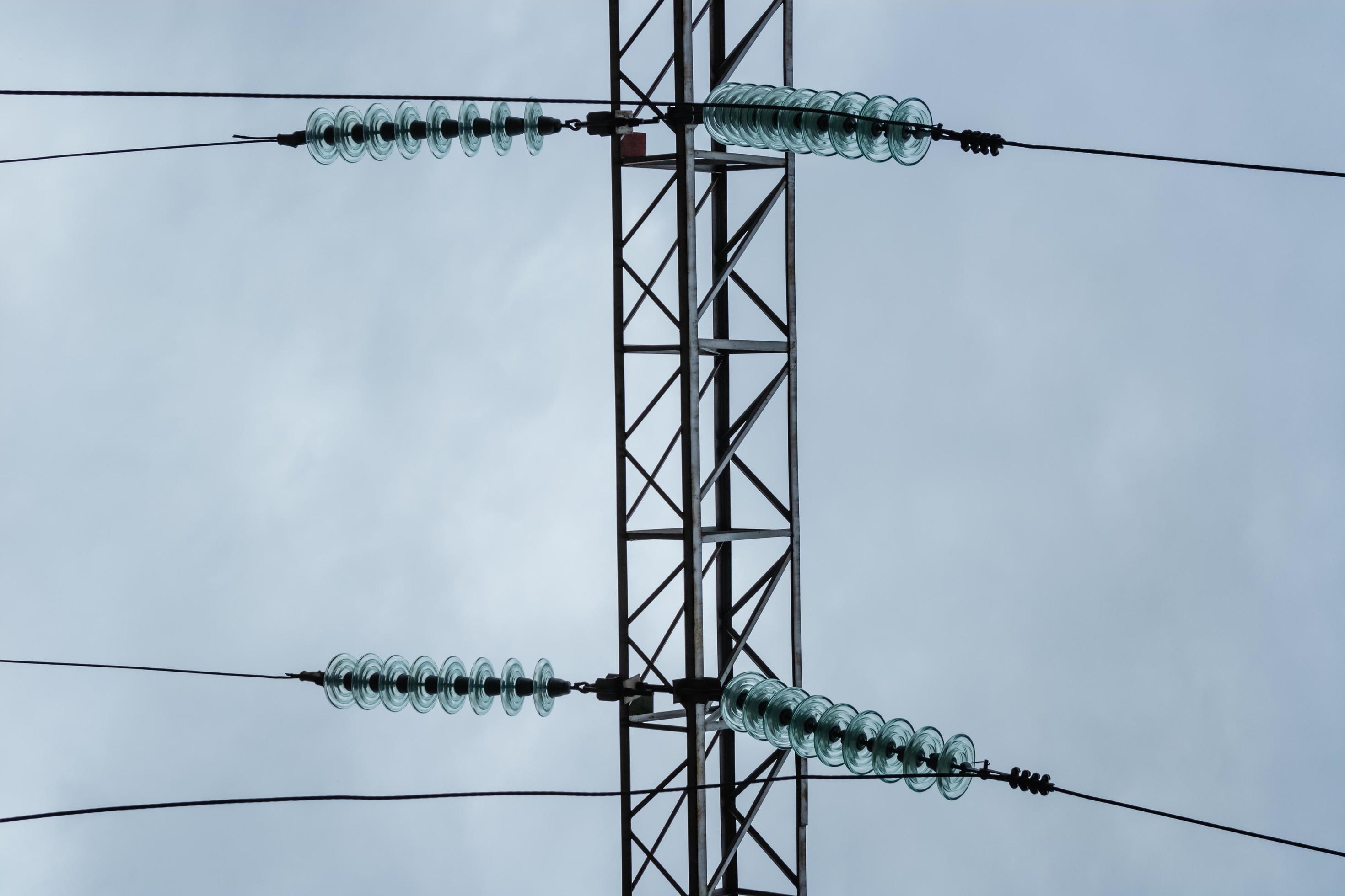
Why Tempered Glass Insulators Are Superior to Porcelain and Composite Insulators for KPLC Substations
KPLC evaluated three insulator materials for its 132kV substations: porcelain, composite (silicone rubber), and tempered glass. After rigorous testing, tempered glass was selected as the optimal choice—primarily due to its superior performance in Kenya’s pollution conditions and alignment with KPLC’s maintenance goals. Here’s why tempered glass outperforms the alternatives:
1. Superior Pollution Resistance:
○ Tempered glass has a smooth, non-porous surface that repels water and contaminants, preventing the formation of conductive films. Porcelain, by contrast, is porous and hydrophilic (absorbs water), making it prone to pollution-induced flashover in industrial and coastal zones. Composite insulators (silicone rubber) are hydrophobic but can degrade over time due to UV radiation and ozone exposure—especially in Kenya’s intense tropical sunlight.
○ Tempered glass insulators with anti-pollution glaze (corrugated surface) provide extended creepage distance in a compact design, making them ideal for substation applications where space is limited. This is critical for KPLC’s urban substations, which are often located in dense areas with limited space for large insulators.
2. Visual Inspectability:
○ A key advantage of tempered glass insulators is their “self-explosion” feature: if the glass core is damaged (e.g., by impact, fatigue, or pollution-induced stress), it shatters into small, harmless pieces, making the failure immediately visible to ground observers. This eliminates the need for costly tower-climbing or specialized equipment to inspect insulators—critical for KPLC, which faces challenges with inadequate maintenance resources (as noted in EE Kenya’s analysis of KPLC’s power outage causes).
○ Porcelain insulators can develop hidden cracks or internal damage that is not visible to the naked eye, leading to sudden failure. Composite insulators can degrade internally without any external signs, making inspection difficult and increasing the risk of unplanned outages.
3. Durability and Longevity:
○ Tempered glass is highly resistant to UV radiation, salt corrosion, and industrial chemicals—critical for Kenya’s tropical climate and polluted environments. It has a service life of 30+ years, compared to 20 years for porcelain and 15–20 years for composite insulators (which degrade faster in UV-rich environments).
○ Tempered glass insulators require minimal maintenance (only occasional cleaning in severe pollution zones), reducing operational costs for KPLC. This aligns with the World Bank’s recommendation to enhance maintenance practices to improve power supply reliability in Kenya.
4. Cost Efficiency:
○ While tempered glass insulators have a slightly higher upfront cost than porcelain, their longer service life and lower maintenance requirements make them more cost-effective over the total lifecycle. For KPLC, which faces financial constraints, this long-term cost savings is critical for sustainable infrastructure management.
○ Composite insulators have a lower upfront cost but require more frequent replacement (every 15–20 years), increasing long-term costs. Porcelain insulators have higher maintenance costs (frequent inspections, cleaning) and a shorter service life, making them less cost-effective than glass.
These advantages make tempered glass insulators the only viable choice for KPLC’s 132kV substations, ensuring long-term reliability in Kenya’s diverse pollution environments while aligning with KPLC’s goals to reduce outages and maintenance costs.
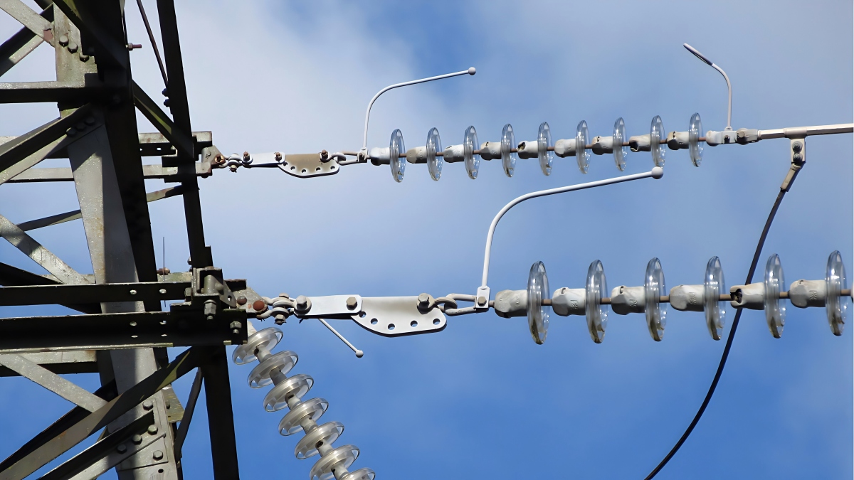
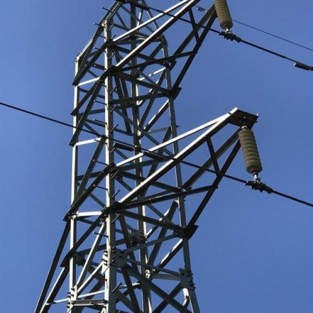
4. Step Four: Installation Structure Alignment – Post-Type Insulators for 132kV Substation Applications
Unlike overhead transmission lines (which use suspension insulators), 132kV substations require insulators that support busbars, circuit breakers, and other equipment—dictating the use of post-type tempered glass insulators as the primary insulator type. Post insulators are designed to be mounted vertically or horizontally on substation structures (concrete foundations, steel frames) and provide both insulation and mechanical support for live equipment. This structural alignment is critical for KPLC’s substations, which must maximize space efficiency and ensure safe, reliable operation of high-voltage equipment.
Why Post-Type Insulators Are Ideal for 132kV Substations
Post-type insulators offer three key benefits that make them perfectly suited for KPLC’s 132kV substations, aligning with IEC 60168 standards and KPLC’s operational requirements:
1. Rigid Support for Busbars and Equipment:
○ Post insulators have a solid, one-piece design (tempered glass core with metal flanges at the top and bottom) that provides rigid support for busbars and equipment. This is critical for 132kV substations, where busbars carry high currents and must remain stable to prevent short circuits. Unlike suspension insulators (which are flexible), post insulators do not sway or bend under wind loads, ensuring consistent insulation clearance between live parts and ground.
○ KPLC’s 132kV substations use both vertical and horizontal post insulators: vertical post insulators support busbars in a vertical orientation (e.g., between transformer windings and circuit breakers), while horizontal post insulators support busbars in a horizontal orientation (e.g., across substation bays). Both types are designed to withstand the specific mechanical loads of their orientation (vertical for compressive loads, horizontal for cantilever loads).
2. Space Efficiency:
○ Substations are often located in urban or dense areas (e.g., Nairobi’s industrial districts) where space is limited. Post-type insulators have a compact design, with a small footprint and vertical orientation that maximizes space efficiency. This allows KPLC to install more equipment in a smaller area, reducing land acquisition costs and simplifying substation design.
○ Unlike suspension insulator strings (which require horizontal space to hang), post insulators can be mounted closely together, making them ideal for substation busbar arrangements (e.g., double busbars, ring busbars) that require high density of insulation points.
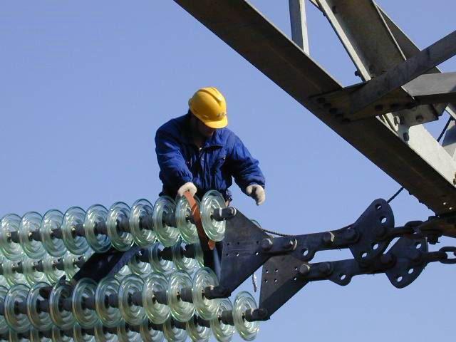
3. Ease of Installation and Maintenance:
○ Post insulators are mounted using flanges (at the top and bottom) that bolt directly to substation structures, making installation quick and straightforward. This is critical for KPLC’s project timeline, which requires the rapid construction and upgrade of 18 substations across the country.
○ Maintenance is simplified by the post insulator’s design: if a single insulator fails, it can be replaced without removing the entire busbar or equipment—unlike suspension strings, which require disconnecting the conductor. This reduces downtime during maintenance, ensuring the substation remains operational for longer periods—critical for KPLC’s goal to reduce power outages (as noted in the World Bank’s IEG review of Kenya’s Electricity Modernization Project).
Tailoring Post Insulator Design to KPLC Substation Equipment
KPLC’s 132kV substations use a range of equipment (transformers, circuit breakers, switchgear, busbars), each requiring a specific post insulator design. The following are the key post insulator types selected for KPLC’s project, aligned with the equipment they support:
1. Busbar Support Post Insulators:
○ Application: Support 132kV rigid busbars (aluminum or copper) in both vertical and horizontal orientations.
○ Design Features: Height of 1500–1800mm (to meet insulation clearance requirements), 4.0–6.3kN cantilever breaking load, 3350mm creepage distance (for severe pollution zones), and flange mounting (top and bottom) for secure attachment to substation structures. These insulators are designed to support busbar weights up to 120kg per meter, aligning with Northern Powergrid’s technical specifications.
○ Example: In Nairobi’s industrial substations, horizontal busbar support post insulators (6.3kN cantilever breaking load) are used to withstand wind loads and busbar tension, while vertical post insulators (4.0kN cantilever breaking load) support vertical busbars between transformers and circuit breakers.
2. Circuit Breaker Post Insulators:
○ Application: Insulate and support 132kV circuit breaker contacts, which carry high currents and are exposed to transient overvoltages.
○ Design Features: Height of 1800–2000mm (to provide additional insulation for circuit breaker contacts), 80kN compressive breaking load, 3350mm creepage distance, and reinforced glass core to withstand vibration from circuit breaker operation. These insulators must meet IEC 60168 standards for circuit breaker insulators, ensuring they can withstand the electrical stresses of switching operations.
○ Example: In Mombasa’s coastal substations, circuit breaker post insulators with anti-corrosion flanges are used to resist salt-induced degradation, while the extended creepage distance prevents flashover from salt fog.
3. Transformer Bushing Post Insulators:
○ Application: Insulate the connection between transformer windings and 132kV busbars, preventing current leakage and ensuring safe power transfer.
○ Design Features: Height of 1500mm, 80kN compressive breaking load, 3350mm creepage distance, and a specialized flange design that connects to transformer bushings. These insulators are designed to withstand high temperatures (up to 100°C) from transformer operation, ensuring long-term reliability.
○ Example: In Nakuru’s rural substations, transformer bushing post insulators with smooth anti-pollution glaze are used to resist agricultural dust, while the high-temperature resistance ensures they can operate safely near transformers.
This tailored approach ensures that each post insulator is perfectly matched to the equipment it supports, maximizing performance and reliability. By aligning the insulator design with the substation’s structural requirements, KPLC can ensure safe, efficient operation of its 132kV substations for decades.
5. Step Five: Connection Type Matching – Ensuring Compatibility with KPLC’s Substation Hardware
The final step in insulator selection is matching the insulator’s connection type to KPLC’s existing substation hardware (e.g., concrete foundations, steel frames, busbars, circuit breakers). For 132kV post insulators, the standard connection type is flange mounting—the industry standard for substation post insulators, as specified in IEC 60168 and Northern Powergrid’s technical specifications (NPS/003/015). This connection type ensures seamless integration with KPLC’s existing infrastructure, reducing installation time and costs while minimizing the risk of connection failures.
Why Flange Mounting Is Preferred for KPLC’s 132kV Substations
Flange mounting offers four critical advantages for KPLC’s 132kV substations, aligning with the company’s operational goals and global substation standards:
1. Compatibility with Existing Hardware:
○ KPLC’s existing substation infrastructure (concrete foundations, steel frames) is designed for flange-mounted insulators, with pre-drilled holes and bolt patterns that match standard flange dimensions. The selected post insulators have flanges with a pitch circle diameter of 127mm and M16 thread size—consistent with Northern Powergrid’s NPS/003/015 specification and KPLC’s existing hardware. This eliminates the need for costly retrofits or custom parts, reducing project timelines by 15–20%.
○ Flange mounting also ensures compatibility with KPLC’s new equipment (e.g., circuit breakers, transformers), which are sourced from global suppliers (e.g., Siemens, ABB) that use standard flange dimensions. This ensures seamless integration between insulators and equipment, reducing the risk of installation errors.
2. Secure Mechanical Attachment:
○ Flange mounting uses high-strength bolts (hot-dip galvanized steel) to secure the insulator to substation structures, providing a rigid, vibration-resistant connection. This is critical for 132kV substations, where vibration from equipment can loosen connections over time. The flange design distributes the mechanical load evenly across the insulator’s base, reducing stress and minimizing the risk of failure.
○ For coastal and high-wind areas, additional locking bolts are used to reinforce the flange connection, ensuring the insulator remains securely mounted even during extreme wind events.
3. Ease of Installation and Replacement:
○ Flange-mounted insulators are quick to install: the insulator is positioned on the foundation or steel frame, and bolts are tightened to secure the flange. This simplicity is critical for KPLC’s project, which requires the rapid construction and upgrade of 18 substations across the country—often in remote areas with limited access to specialized tools and labor.
○ Replacement is equally straightforward: if an insulator fails, the bolts are removed, and the old insulator is replaced with a new one—without disconnecting the busbar or equipment. This reduces downtime during maintenance, ensuring the substation remains operational for longer periods—critical for KPLC’s goal to reduce power outages.
4. Corrosion Resistance:
○ The flanges are made of hot-dip galvanized steel, which provides superior corrosion resistance—critical for Kenya’s coastal and industrial environments. Hot-dip galvanization forms a protective zinc layer that prevents rust and degradation from salt fog, industrial chemicals, and moisture. For coastal substations, the flanges are also coated with an anti-corrosion paint to provide additional protection against salt-induced damage.
○ This corrosion resistance ensures the flange connection remains secure for the insulator’s entire service life (30+ years), reducing maintenance costs and minimizing the risk of connection failure.
Flange Design Specifications for KPLC’s Substations
To ensure compatibility and performance, the flange design for KPLC’s 132kV post insulators must meet the following specifications (aligned with IEC 60168 and Northern Powergrid’s NPS/003/015):
• Material: Hot-dip galvanized steel (minimum tensile strength 400MPa) for corrosion resistance.
• Dimensions: Pitch circle diameter (PCD) of 127mm, 4–6 bolt holes (M16 thread size), flange thickness of 16mm—consistent with KPLC’s existing hardware.
• Mounting Type: Bottom flange (for vertical post insulators) and top flange (for horizontal post insulators), with rubber gaskets to prevent moisture ingress between the flange and substation structure.
• Corrosion Protection: Hot-dip galvanization (minimum zinc coating thickness of 80μm) plus anti-corrosion paint (for coastal and industrial substations) to resist salt and industrial contamination.
By adhering to these specifications, the selected insulators ensure full compatibility with KPLC’s substation hardware, minimizing installation errors and maximizing operational reliability. This attention to connection detail is critical—even a small mismatch in flange dimensions can cause installation delays, increase costs, and compromise the insulator’s mechanical performance.
6. Recommended Insulator Solution for Kenya’s 132kV KPLC Substation Project
Based on the comprehensive selection process outlined above—voltage level analysis, mechanical load assessment, pollution environment evaluation, installation structure alignment, and connection type matching—the recommended tempered glass insulator for Kenya’s 132kV KPLC Substation Project is tailored to each pollution zone and substation location. The following is the detailed specification for the primary insulator types used in the project, aligned with IEC standards, KPLC’s technical requirements, and Kenya’s environmental conditions:
Parameter | Urban Industrial Substations (IEC Class IV) | Rural Agricultural Substations (IEC Class II–III) | Coastal Substations (IEC Class IV) |
Product Name & Model | EN: 132kV Anti-Pollution Tempered Glass Post Insulator (6.3kN Cantilever, Flange Mounting)CN: 132kV | EN: 132kV Anti-Pollution Tempered Glass Post Insulator (4.0kN Cantilever, Flange Mounting)CN: 132kV | EN: 132kV Anti-Corrosion & Anti-Pollution Tempered Glass Post Insulator (6.3kN Cantilever, Flange Mounting)CN: 132kV |
Main Standard | IEC 60168 (Station Post Insulators), IEC 60273 (Overhead Line Insulators), KPLC Technical Specification | IEC 60168 (Station Post Insulators), IEC 60273 (Overhead Line Insulators), KPLC Technical Specification | IEC 60168 (Station Post Insulators), IEC 60273 (Overhead Line Insulators), KPLC Technical Specification |
Rated Voltage Level | 132 kV (145 kV nominal maximum) / For 132kV substation busbar, circuit breaker, and transformer support132 kV | 132 kV (145 kV nominal maximum) / For 132kV substation busbar, circuit breaker, and transformer support132 kV | 132 kV (145 kV nominal maximum) / For 132kV substation busbar, circuit breaker, and transformer support in coastal salt fog zones132 kV( |
Withstand Voltage | Power Frequency: 275 kV rms (1 min)Lightning Impulse: 650 kV peak (1.250μs)Switching Impulse: 550 kV peak (250/2500μs) | Power Frequency: 275 kV rms (1 min)Lightning Impulse: 650 kV peak (1.250μs)Switching Impulse: 550 kV peak (250/2500μs) | Power Frequency: 275 kV rms (1 min)Lightning Impulse: 650 kV peak (1.250μs)Switching Impulse: 550 kV peak (250/2500μs) |
Mechanical Load | Cantilever Breaking Load: 6.3 kNCompressive Breaking Load: 80 kNTorsional Breaking Load: 3.0 kNmMaximum Busbar Weight: 120 kg/m | Cantilever Breaking Load: 4.0 kNCompressive Breaking Load: 80 kNTorsional Breaking Load: 3.0 kNmMaximum Busbar Weight: 120 kgm | Cantilever Breaking Load: 6.3 kNCompressive Breaking Load: 100 kNTorsional Breaking Load: 3.0 kNmMaximum Busbar Weight: 120 kgm |
Insulation Distance | Creepage Distance: 3350 mm (anti-pollution corrugated surface)Clearance: 1500 mmInsulator Height: 1800 mm | Creepage Distance: 3350 mm (anti-pollution smooth surface)Clearance: 1500 mmInsulator Height: 1500 mm | Creepage Distance: 3350 mm (anti-pollution corrugated surface)Clearance: 1500 mmInsulator Height: 1800 mm |
Material | Core: Tempered Glass (high-strength, UV-resistant)Surface: Corrugated anti-pollution glazeFlange: Hot-dip galvanized steel | Core: Tempered Glass (high-strength, UV-resistant)Surface: Smooth anti-pollution glazeFlange: Hot-dip galvanized steel | Core: Tempered Glass (high-strength, UV-resistant)Surface: Corrugated anti-pollution + anti-corrosion glazeFlange: Hot-dip galvanized steel + anti-corrosion paint |
Connector/Fitting | Type: Flange Mounting (PCD 127mm, M16 bolts)Material: Hot-dip galvanized steel bolts + rubber gaskets | Type: Flange Mounting (PCD 127mm, M16 bolts)Material: Hot-dip galvanized steel bolts + rubber gaskets | Type: Flange Mounting (PCD 127mm, M16 bolts)Material: Stainless steel bolts + rubber gaskets + anti-corrosion washers |
Quality & Test Reports |
