
Glass Electrical Insulators: The Unsung Heroes of Modern Power Grids-01
")
1.Introduction: The Critical Role of Insulation in Power Transmission
1.1 Defining the Electrical Insulator
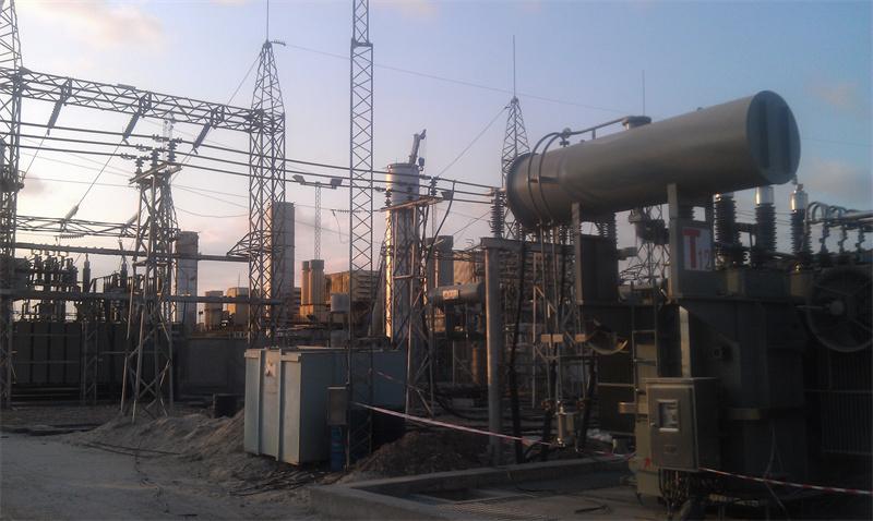
An electrical insulator is a fundamental component in any power transmission and distribution system, serving the dual purpose of mechanically supporting and electrically isolating conductors from their supporting structures and the ground. These devices are critical for ensuring the safe and efficient flow of electricity over long distances. Without insulators, the high-voltage current carried by power lines would arc to the nearest grounded object, causing short circuits, power outages, and posing a significant safety hazard. Insulators are typically made from materials with very high electrical resistance, such as glass, porcelain, or polymer composites, which prevent the flow of electric current. The primary function of an insulator is to create a physical barrier that is strong enough to withstand both the electrical stress from the high voltage and the mechanical stress from the weight of the conductors, wind, and other environmental factors. In essence, they are the silent guardians of the electrical grid, enabling the reliable delivery of power to homes, industries, and cities worldwide .
The design and material of an insulator are chosen based on the specific application, voltage level, and environmental conditions. For instance, insulators used on high-voltage transmission lines must be able to withstand extreme electrical fields, while those in coastal areas need to resist corrosion from salt spray. The most common types of insulators include pin-type, suspension, post, and strain insulators, each with a unique design tailored to its specific role in the power grid. Pin-type insulators are typically used for lower voltage distribution lines, while suspension insulators, often seen as strings of discs hanging from transmission towers, are designed for high-voltage applications. The choice of material also plays a crucial role in the insulator's performance. Glass insulators, for example, are known for their high mechanical strength, excellent electrical properties, and long service life, making them a popular choice for many utilities. The continuous evolution of insulator technology is driven by the growing demand for electricity, the need for more reliable and resilient power grids, and the increasing focus on sustainability and environmental impact .
1.2 The Evolution of Insulator Materials
The history of electrical insulators is a story of continuous innovation, driven by the ever-increasing demands of power systems for higher voltages, greater reliability, and improved performance. In the early days of electrical engineering, the first insulators were made from simple materials like glass and porcelain, which were readily available and offered good electrical resistance . Glass tubes were used as early as 1816, and by the late 19th century, both glass and porcelain had become the standard materials for insulating telegraph and power lines. These materials were chosen for their durability and high electrical resistance, which were sufficient for the relatively low voltages of the time . As power systems evolved and voltages climbed, the limitations of these early materials became apparent, spurring research into new insulating materials and designs.
The 20th century saw the introduction of new materials that revolutionized the field of electrical insulation. The development of vulcanized rubber in 1844 and the subsequent use of natural rubber and gutta-percha provided more flexible insulation for cables . The invention of synthetic polymers in the mid-20th century, such as PVC in 1933 and polyethylene in 1942, opened up new possibilities for insulating materials with improved properties. These polymer-based insulators offered advantages such as lighter weight, better resistance to vandalism, and superior performance in contaminated environments compared to traditional ceramic and glass insulators . In the late 1970s and early 1980s, composite insulators, which typically consist of a fiberglass core and a polymer housing, began to be used for specialized applications. These insulators combined the high mechanical strength of fiberglass with the excellent electrical properties and hydrophobicity of silicone rubber, making them ideal for challenging environments. Today, the choice of insulator material—be it glass, porcelain, or polymer—is a critical engineering decision that depends on a complex interplay of factors including cost, performance, environmental conditions, and the specific requirements of the power system .
1.3 Why Glass? A Preview of Key Advantages
Glass has emerged as a premier material for electrical insulators, offering a compelling combination of electrical, mechanical, and environmental advantages that make it a superior choice for many high-voltage applications. One of the most significant benefits of glass insulators is their exceptional electrical performance. Glass is an excellent electrical insulator with high dielectric strength, meaning it can withstand high voltages without breaking down. This property is crucial for preventing flashovers, which can lead to power outages and damage to equipment. Additionally, glass insulators have a low dielectric loss, which minimizes energy dissipation and improves the overall efficiency of the power transmission system. The smooth, non-porous surface of glass also helps to shed water and contaminants, reducing the risk of leakage currents and maintaining high insulation resistance even in polluted or wet conditions. This self-cleaning characteristic is particularly valuable in areas with high levels of industrial pollution or salt spray, where other types of insulators may require frequent cleaning to maintain their performance.
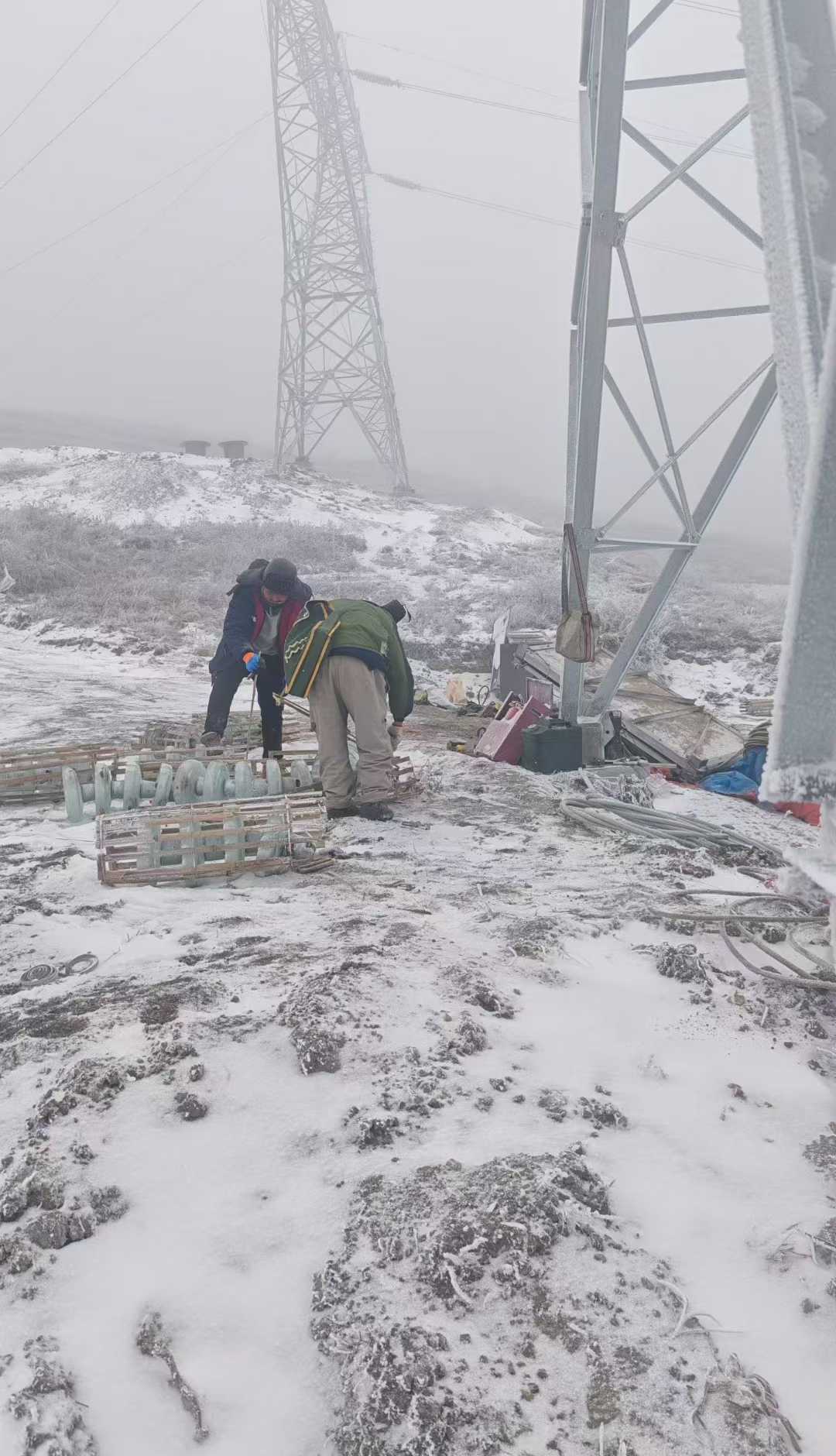
")
Beyond their electrical properties, glass insulators are renowned for their exceptional mechanical strength and durability. Made from toughened or tempered glass, these insulators can withstand significant mechanical loads, including the weight of heavy conductors and the forces exerted by wind and ice. This high mechanical strength ensures a long service life and reduces the need for frequent replacements, which can be costly and disruptive. Another unique advantage of glass insulators is their transparency. This allows for easy visual inspection, enabling maintenance crews to quickly identify any internal defects, such as cracks or punctures, that could compromise the insulator's integrity. This transparency is a significant safety feature, as it allows for the early detection of potential failures before they lead to a catastrophic event. Furthermore, glass insulators have a predictable failure mode. When a glass insulator fails, it typically shatters into small, relatively harmless pieces, making it immediately obvious that a replacement is needed. This is in contrast to other materials, such as porcelain, which may fail internally without any visible signs of damage, creating a hidden hazard. The combination of these advantages makes glass insulators a reliable, safe, and cost-effective solution for modern power grids.
2. A Deep Dive into Glass Insulator Types and Applications
2.1 Pin-Type Insulators: The Workhorses of Distribution Networks
Pin-type insulators are one of the oldest and most common designs for supporting conductors on utility poles, particularly in low- and medium-voltage distribution networks. As their name suggests, these insulators are mounted on a pin, which is a metal or wooden rod that is secured to the crossarm of a utility pole. The insulator itself is a single, solid piece of insulating material, typically porcelain or glass, with a groove or groove at the top where the conductor is seated and tied down. The design is relatively simple and robust, providing both electrical insulation and mechanical support in a compact and cost-effective package. The primary function of a pin insulator is to support the weight of the conductor and to insulate it from the grounded pole structure, preventing current leakage and ensuring the safe and reliable operation of the distribution line .
The construction of a pin-type glass insulator involves a single, solid piece of toughened glass that is molded into a shape with a series of petticoats or skirts. These skirts serve to increase the surface area of the insulator, which in turn increases the creepage distance—the path that a leakage current would have to travel along the surface of the insulator. A longer creepage distance improves the insulator's performance in wet or polluted conditions, as it makes it more difficult for a flashover to occur. The insulator has a threaded hole in its base, which allows it to be screwed onto the mounting pin. The top of the insulator features a groove or grooves designed to accommodate the conductor, which is then secured with a wire tie. The entire assembly is designed to be strong enough to support the weight of the conductor and to withstand the mechanical stresses of wind and ice loading, while providing the necessary electrical insulation to prevent faults.
2.1.1 Design and Construction
The design and construction of pin-type glass insulators are centered around simplicity, durability, and reliable performance in medium-voltage applications. The main body of the insulator is a single, solid piece of toughened glass, which is manufactured through a process of melting, molding, and thermal tempering. This tempering process creates a state of high compressive stress on the surface of the glass, significantly enhancing its mechanical strength and resistance to impact and thermal shock. The glass is typically formulated with a high silica content and other additives to optimize its electrical insulating properties, such as high dielectric strength and low electrical loss. The external shape of the insulator is designed with a series of petticoats or skirts, which serve to increase the creepage distance—the path length along the surface of the insulator between the live conductor and the grounded pin. This increased path length helps to prevent flashover, particularly in wet or polluted conditions.
The construction of a pin-type insulator involves the integration of the glass body with metal fittings. The base of the insulator is designed to be mounted on a pin, which is typically made of galvanized steel for corrosion resistance. This pin is then secured to the cross-arm of a utility pole. The top of the insulator features a head or groove designed to securely hold the conductor wire. In some designs, a separate tie wire is used to fasten the conductor to the insulator, while in others, the conductor is simply laid in a pre-formed groove. The interface between the glass and the metal pin is a critical area of design, as it must provide a strong, durable bond that can withstand both mechanical loads and electrical stress without degrading over time. The overall construction is robust and designed for a long service life, often exceeding 30 years, with minimal maintenance required.
2.1.2 Typical Voltage Ranges and Applications
Pin-type glass insulators are predominantly used in medium-voltage distribution networks, with typical voltage ratings ranging from **11kV to 33kV**. This voltage range covers the majority of local distribution lines that deliver electricity from substations to residential, commercial, and light industrial customers. The design of the pin-type insulator is well-suited for these voltage levels, providing adequate electrical insulation and mechanical support without the complexity and cost of suspension insulator strings. The single-unit construction is a key advantage in these applications, as it simplifies installation and reduces the number of components that could potentially fail. The insulators are designed to withstand the electrical stresses of the system voltage, as well as temporary overvoltages that can occur due to switching operations or lightning strikes.
The primary application for pin-type glass insulators is on overhead distribution lines, where they are mounted on wooden, concrete, or steel poles. They are used to support the phase conductors, keeping them spaced apart and insulated from the grounded pole structure. In addition to their use on standard distribution lines, pin-type insulators can also be found in other applications, such as on guy wires to insulate them from the ground, and in some low-voltage applications where a robust and reliable insulator is required. Their versatility and reliability have made them a standard component in the electrical distribution infrastructure of many countries around the world. The ability to easily inspect them for damage, thanks to the transparency of the glass, is a significant operational advantage, allowing for proactive maintenance and replacement before a failure occurs.
2.1.3 Installation on Utility Poles
The installation of pin-type glass insulators is a relatively straightforward process, typically carried out by lineworkers or high voltage electricians.
The process begins with securing the pin to the cross-arm of the utility pole.
The pin is threaded and screwed into a pre-drilled hole in the cross-arm, ensuring it is firmly attached and can support the weight of the insulator and conductor. Once the pin is in place, the glass insulator is placed over the pin and secured with a locking nut or a similar fastening device.
The conductor is then laid in the groove at the top of the insulator and secured with wire ties or preformed armor rods. These ties are carefully applied to ensure the conductor is held firmly without being damaged. Proper installation is crucial for the long-term performance of the insulator. An improperly installed insulator can lead to premature failure, either due to mechanical stress or electrical tracking across the surface. Therefore, utility companies have strict standards and procedures for the installation of all types of insulators, including pin-type glass insulators.
2.2 Suspension Insulators: The Backbone of High-Voltage Transmission
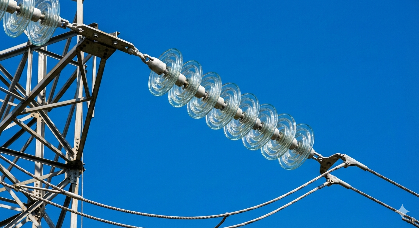
Suspension insulators are the workhorses of high-voltage (HV), extra-high-voltage (EHV), and ultra-high-voltage (UHV) transmission systems. Unlike pin-type insulators, which are designed to support the conductor from below, suspension insulators hang from the crossarm of a transmission tower and support the conductor from above. This design allows them to be used in strings of multiple insulator units, which can be assembled to achieve the necessary electrical insulation and mechanical strength for very high voltage levels. Each unit in the string is a disc-shaped insulator, typically made of toughened glass or porcelain, with a metal cap on one end and a metal pin on the other. The units are connected together in a chain, with the top unit of the string attached to the tower and the bottom unit connected to the conductor via a clamp. This modular design provides great flexibility, as the number of units in the string can be varied to suit the specific voltage and environmental conditions of the transmission line .
The use of suspension insulators is essential for the long-distance, high-capacity power transmission that forms the backbone of modern electrical grids. As the voltage of a transmission line increases, the required insulation level also increases. A single-piece insulator, like a pin-type, would need to be extremely large and heavy to provide adequate insulation for a 500 kV or 765 kV line, making it impractical to manufacture, transport, and install. By using a string of smaller, lighter disc insulators, the required insulation level can be achieved by simply adding more units to the string. This modular approach also provides redundancy; if one unit in the string fails, the remaining units can continue to support the conductor, preventing an immediate line outage. This makes suspension insulators a highly reliable and scalable solution for high-voltage applications.
2.2.1 String Configuration for High Voltages
The string configuration of suspension insulators is a key design feature that allows them to be used in high-voltage transmission systems. By connecting multiple insulator units in series, a string of the required electrical strength can be assembled to match the system voltage. Each glass disc in the string is designed to withstand a certain voltage, and by adding more discs, the overall voltage withstand capability of the string is increased. The number of discs in a string is not arbitrary; it is carefully calculated based on the nominal system voltage, the maximum expected overvoltages (such as those from lightning or switching surges), and the environmental conditions of the installation site. For example, a transmission line operating at **220kV might use a string of 14 to 16 glass insulator discs**, while a **500kV line could require 25 or more discs**.
")
The mechanical design of the string is also critical. The insulator discs are connected using ball-and-socket or clevis-and-tongue fittings, which allow for a degree of flexibility and articulation. This flexibility is important for accommodating the movement of the conductor due to thermal expansion and contraction, as well as dynamic loads from wind. The entire string is suspended from the transmission tower, and the conductor is attached to the bottom of the string using a similar fitting. This configuration ensures that the mechanical tension of the conductor is transferred through the insulator string to the tower, while the electrical insulation is maintained. The use of a string of individual units also provides a degree of redundancy; if one disc in the string were to fail, the remaining discs would continue to provide some level of insulation, although the string would need to be replaced as soon as possible to restore the system to its full design strength.
2.2.2 Use on Transmission Towers and Pylons
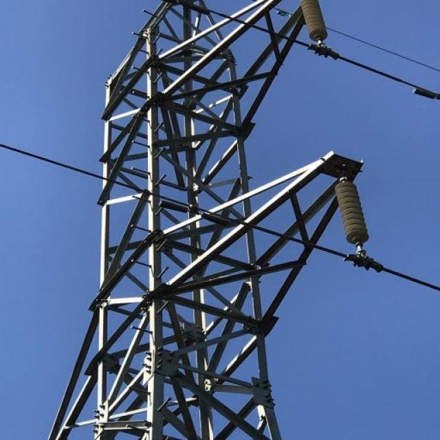
Suspension glass insulators are an integral component of transmission towers and pylons, which are the massive steel structures that support high-voltage power lines over long distances. These towers are designed to carry multiple circuits of three-phase power, with each phase conductor suspended from the tower by an insulator string. The insulators are typically attached to the cross-arms of the tower, which are the horizontal beams that extend from the main body of the structure. The arrangement of the insulator strings on the tower is carefully designed to maintain the required electrical clearances between the conductors of different phases, as well as between the conductors and the grounded tower structure. This is essential for preventing electrical faults and ensuring the safe operation of the transmission line.
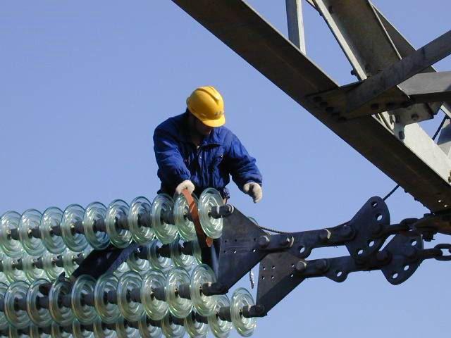
The use of suspension insulators on transmission towers allows for the efficient and reliable transmission of large amounts of power over long distances. The high mechanical strength of the toughened glass insulators is well-suited to the demanding environment of a transmission line, where they must withstand not only the static load of the conductor but also dynamic loads from wind, ice, and seismic events. The long strings of insulators provide the necessary electrical insulation to prevent flashover, even under the high electrical stresses of EHV transmission. The transparency of the glass insulators is a significant advantage for maintenance, as it allows for visual inspection of the internal structure of the insulator for any signs of damage or deterioration. This helps to ensure the long-term reliability of the transmission system and allows for proactive maintenance to prevent failures.
2.2.3 Flexibility and Mechanical Load Distribution
The suspension configuration of these insulators provides a high degree of flexibility, which is a major advantage in high-voltage applications. The ability of the insulator string to swing and pivot helps to distribute the mechanical loads more evenly, reducing the stress on any single point. This is particularly important in areas with high winds or seismic activity, where the transmission line is subjected to significant dynamic forces. The flexibility of the suspension string also allows for some movement of the conductor, which helps to prevent damage from thermal expansion and contraction. This is a critical consideration for long transmission lines, where temperature changes can cause the conductor to expand and contract by several feet. The ability of the suspension insulator string to accommodate this movement is essential for maintaining the integrity of the line and preventing conductor breakage. The combination of high strength, flexibility, and ease of inspection makes suspension glass insulators the preferred choice for many high-voltage transmission applications.
2.3 Post Insulators: Rigid Support in Substations
Post insulators are a type of rigid insulator used to support and isolate conductors in substations and other electrical equipment. Unlike suspension insulators, which are flexible, post insulators are designed to be rigid and provide a stable, non-moving support. They are typically cylindrical in shape, with a series of skirts or sheds to increase the surface leakage distance, similar to pin-type insulators. Post insulators can be mounted either vertically or horizontally, depending on the specific application. In a vertical mounting, the insulator stands upright, supporting a busbar or other conductor from below. In a horizontal mounting, the insulator is laid on its side, supporting a conductor from the side. The ability to mount post insulators in either orientation provides great flexibility in the design and layout of substations and other electrical facilities.
2.3.1 Vertical and Horizontal Mounting
Post insulators are designed for versatility in mounting, allowing them to be installed in either a vertical or horizontal orientation to suit the specific requirements of the application. In a vertical mounting configuration, the insulator stands upright, supporting equipment from below. This is a common arrangement for supporting busbars in open-air substations, where the post insulators are mounted on a grounded structure and the busbar is supported on top. The vertical orientation provides a stable and secure support, and the height of the insulator can be adjusted to provide the necessary electrical clearance from the ground and other equipment. The mechanical strength of the post insulator in compression is a critical factor in this application, as it must be able to support the weight of the busbar and any additional loads, such as the forces from wind or short-circuit currents.
In a horizontal mounting configuration, the post insulator is laid on its side, supporting equipment from the side. This arrangement is often used in switchgear and other enclosed equipment, where space is limited and a vertical mounting is not feasible. For example, post insulators can be used to support the moving contacts of a disconnect switch, allowing them to open and close while remaining insulated from the grounded enclosure. In this orientation, the insulator must be able to withstand both compressive and tensile loads, as well as bending moments. The design of the post insulator, including the strength of the glass column and the robustness of the end fittings, must be carefully considered to ensure that it can withstand these complex mechanical stresses. The ability to mount post insulators in either a vertical or horizontal orientation makes them a highly flexible and adaptable solution for a wide range of high-voltage applications.
2.3.2 Applications in Switchgear and Transformers
Post insulators play a crucial role in the construction and operation of switchgear and transformers, which are key components of the electrical power system. In switchgear, which is used to control, protect, and isolate electrical equipment, post insulators are used to support and insulate the various components, such as circuit breakers, disconnect switches, and busbars. They provide the necessary electrical insulation to prevent flashover between the live parts of the switchgear and the grounded enclosure, ensuring the safe operation of the equipment. The rigid support provided by the post insulators is also essential for maintaining the proper alignment and spacing of the components, which is critical for the reliable operation of the switchgear. The compact design of modern switchgear often requires the use of post insulators with a high mechanical strength and a high electrical performance in a small package.
In transformers, post insulators are used to bring the high-voltage and low-voltage connections out of the transformer tank while maintaining electrical insulation. These are often referred to as bushing insulators, and they are a critical component of the transformer, as they must be able to withstand the high electrical stresses of the system voltage, as well as the thermal and mechanical stresses of the transformer's operation. The bushing insulator is typically a hollow post insulator, with the conductor running through the center. The design of the bushing is complex, as it must provide a uniform electric field distribution to prevent localized high stresses that could lead to a failure. The use of toughened glass in bushing insulators offers the advantages of high strength, excellent electrical properties, and the ability to withstand the harsh environment inside a transformer.
2.3.3 High-Voltage Busbar Support
One of the most common applications for post insulators is the support of high-voltage busbars in substations. Busbars are the conductors that connect the various pieces of electrical equipment in a substation, and they must be securely supported and isolated from the ground and other conductors. Post insulators provide the rigid support needed to keep the busbars in place, while also providing the necessary electrical insulation. The use of multiple post insulators in series can provide the high level of insulation required for very high voltage applications. The reliability of the busbar support system is critical for the safe and efficient operation of the substation, and the use of high-quality post insulators is essential for ensuring this reliability.
2.4 Strain Insulators: Managing Mechanical Tension
Strain insulators, also known as tension or dead-end insulators, are a specialized type of suspension insulator designed to withstand high mechanical tension. They are used at the ends of transmission lines, at points where the line changes direction (angle poles), and at major crossings, such as rivers or highways. In these locations, the conductor is under significant tension, and the insulator must be able to support this tension without failing. Strain insulators are typically used in a horizontal or angled configuration, and they are designed to be much stronger than standard suspension insulators. They are often used in sets of two or more to provide the necessary mechanical strength.
2.4.1 Dead-End and Angle Pole Applications
Dead-end and angle pole applications are the primary use cases for strain insulators, where they are essential for managing the mechanical forces in a transmission line. A dead-end pole is a structure where a transmission line terminates, and the full tension of the conductor is transferred to the pole. In this application, a string of strain insulators is used to connect the conductor to the pole, providing both the necessary electrical insulation and the mechanical anchoring of the line. The strain insulator string must be designed to withstand the maximum tension of the conductor, which can be very high, especially for long spans and heavy conductors. The robust design of strain insulators, with their high mechanical strength, makes them well-suited for this demanding application.
Angle poles are used where a transmission line changes direction, and they are subjected to the resultant force of the conductor tension pulling in two different directions. A strain insulator is used at the point of the angle to manage this tension and to ensure that the pole remains stable. The ability of strain insulators to handle these high mechanical loads is critical for maintaining the structural integrity of the entire transmission line. The use of toughened glass strain insulators provides the added assurance of high mechanical strength and the safety benefits of their self-shattering failure mode.
2.4.2 Handling Conductor Stress
The primary function of a strain insulator is to handle the high mechanical stresses in the conductor. The tension in the conductor can be very high, especially in long spans or in areas with heavy ice loading. The strain insulator must be able to support this tension without breaking or deforming. The use of toughened glass for strain insulators provides the high mechanical strength required for these demanding applications. The insulator's design also plays a critical role in its ability to handle stress. The shape of the insulator and the design of the end fittings are optimized to distribute the mechanical loads evenly, reducing the stress on any single point. The reliability of strain insulators is critical for the integrity of the transmission line, as a failure at a dead-end or angle pole could lead to a cascading failure of the entire line.
2.5 Shackle Insulators: Solutions for Low-Voltage Lines
Shackle insulators, also known as spool insulators, are a simple and inexpensive type of insulator used primarily in low-voltage distribution lines. They are typically made of porcelain or glass and have a spool-like shape with a hole through the center. The insulator is mounted on a bolt or a pin that passes through the central hole, and the conductor is tied to the insulator with wire. The design of the shackle insulator is very simple, which makes it a cost-effective solution for many low-voltage applications. The spool shape provides a certain amount of surface leakage distance, which is adequate for the low voltages at which these insulators are used.
2.5.1 Design for Spool-Type Mounting
The design of shackle insulators is characterized by their spool-like shape, which is optimized for a simple and secure mounting method. The insulator has a central hole that allows it to be mounted on a bolt or pin, which is then attached to a cross-arm or other supporting structure. The conductor is then wrapped around the groove in the middle of the insulator and secured with wire ties. This spool-type mounting is very straightforward and does not require any specialized hardware, which contributes to the low cost and ease of installation of these insulators. The design is also very compact, which makes it suitable for applications where space is limited.
2.5.2 Use in Secondary Distribution
Shackle insulators are most commonly used in secondary distribution lines, which are the lines that deliver electricity from the distribution transformer to the customer's service drop. They are also used for service drops themselves, where they are mounted on the side of a building or on a service pole. In these applications, the insulator's primary function is to support the conductor and provide the necessary electrical insulation. The simplicity and low cost of shackle insulators make them an ideal choice for these widespread, low-voltage applications. While they are not suitable for high-voltage transmission, they play a vital role in the final stage of the power delivery process, ensuring that electricity is safely and reliably delivered to homes and businesses.
3. Performance Characteristics: Why Glass Makes a Good Insulator
3.1 Superior Electrical Properties
Glass insulators are renowned for their excellent electrical properties, which make them a preferred choice for high-voltage applications. One of the most important of these properties is their high dielectric strength. Dielectric strength is a measure of the maximum electric field that a material can withstand without breaking down and becoming conductive. Glass has a very high dielectric strength, which means that it can support a large voltage difference across a small thickness without allowing a current to pass through. This is a critical characteristic for an insulator, as it allows for the design of compact and efficient insulation systems. The high dielectric strength of glass is a result of its rigid, non-crystalline atomic structure, which does not contain any free electrons or ions that could carry an electric current.
In addition to its high dielectric strength, glass also has a very high electrical resistivity. Resistivity is a measure of how strongly a material opposes the flow of electric current. A high resistivity means that even when a voltage is applied across the material, the current that flows through it will be very small. This is important for preventing leakage currents, which can cause power losses and can lead to the degradation of the insulator over time. The high resistivity of glass is due to the strong ionic bonds between its constituent atoms, which hold the electrons tightly in place and prevent them from moving freely. These superior electrical properties, combined with the material's inherent stability, make glass an excellent choice for insulating high-voltage power lines and other electrical equipment.
3.1.1 High Dielectric Strength
The high dielectric strength of glass is a key factor in its effectiveness as an electrical insulator. This property allows glass insulators to be designed with a relatively small size and weight, while still providing the necessary level of electrical insulation for high-voltage applications. The dielectric strength of a material is typically measured in kilovolts per millimeter (kV/mm), and for glass, this value is typically in the range of **10 to 40 kV/mm**. This means that a 1 mm thick layer of glass can withstand a voltage of 10,000 to 40,000 volts without breaking down. This high value is a direct result of the strong atomic bonds in the glass structure, which make it very difficult for electrons to be torn away from their atoms and to create a conductive path through the material .
The high dielectric strength of glass is particularly important in applications where space is limited, such as in compact substations or on narrow transmission towers. By using glass insulators, engineers can design more compact and cost-effective electrical systems without compromising on safety or reliability. The high dielectric strength of glass also contributes to its excellent performance under transient overvoltage conditions, such as those caused by lightning strikes or switching operations. These overvoltages can be many times higher than the normal operating voltage of the system, and the ability of the insulator to withstand these high-voltage surges is critical for preventing flashovers and ensuring the stability of the power grid. The consistent and predictable dielectric strength of glass, combined with its long-term stability, makes it a highly reliable material for critical electrical insulation applications.
3.1.2 Low Dielectric Loss
In addition to high dielectric strength, glass also exhibits low dielectric loss. Dielectric loss is the dissipation of energy in a dielectric material when an alternating electric field is applied. This loss of energy results in the heating of the material, which can lead to a reduction in its insulating properties and, in extreme cases, to thermal runaway and failure. The low dielectric loss of glass means that it is an efficient insulator, with minimal energy wasted as heat. This is particularly important in high-voltage AC applications, where the alternating electric field can cause significant heating in materials with high dielectric loss. The low dielectric loss of glass helps to ensure that the insulator remains cool and maintains its insulating properties, even under high electrical stress.
3.1.3 High Flashover Voltage
Flashover is a type of electrical failure that occurs when an arc forms across the surface of an insulator, creating a conductive path between the conductor and the ground. The voltage at which this occurs is known as the flashover voltage. Glass insulators have a high flashover voltage, which means they are resistant to this type of failure. This is due to a combination of factors, including the smooth, non-porous surface of the glass, which makes it difficult for contaminants to adhere, and the hydrophobic nature of the glass, which causes water to bead up and run off rather than forming a continuous film. The high flashover voltage of glass insulators is a key advantage in polluted or wet environments, where the risk of flashover is high. This property helps to ensure the reliable operation of the power grid, even in adverse weather conditions.
3.2 Exceptional Mechanical Strength
In addition to their excellent electrical properties, glass insulators also possess exceptional mechanical strength, which is a critical requirement for their role in supporting the heavy conductors of a power transmission line. The mechanical strength of an insulator is a measure of its ability to withstand mechanical loads without failing. For glass insulators, this is typically specified in terms of their tensile strength, which is the maximum pulling force that the insulator can withstand before it breaks. The tensile strength of a toughened glass insulator can be as high as **550 kN (kilonewtons)** , which is equivalent to a force of over 55,000 kilograms. This high strength is achieved through a process of thermal tempering, which creates a state of high compressive stress on the surface of the glass, making it much more resistant to mechanical shock and bending loads.
The high mechanical strength of glass insulators is essential for ensuring the structural integrity of the transmission line. The conductors of a high-voltage line can be very heavy, and they are often subjected to additional loads from wind and ice. The insulators must be able to support these loads without breaking or deforming, as a failure of an insulator can lead to a complete collapse of the line. The high strength of glass insulators also makes them more resistant to damage during handling and installation, which can reduce the risk of premature failure and improve the overall reliability of the power system.
3.2.1 Compressive Strength vs. Ceramic
Toughened glass insulators exhibit exceptional mechanical strength, particularly in compression. The tempering process used to manufacture these insulators creates a state of high compressive stress on the surface of the glass, which significantly increases its strength. In fact, the **compressive strength of toughened glass is often higher than that of porcelain**, a material traditionally known for its high strength. This high compressive strength makes glass insulators well-suited for applications where they are subjected to high mechanical loads, such as in suspension and post insulators. The ability of glass insulators to withstand high compressive loads without failing is a key factor in their long-term reliability and performance.
3.2.2 Resistance to Mechanical Shock
In addition to high compressive strength, toughened glass insulators also have excellent resistance to mechanical shock. The tempering process not only increases the strength of the glass but also makes it more resistant to impact. This is a significant advantage in areas where insulators may be subjected to vandalism or to impacts from falling objects, such as tree branches. While a severe impact can cause a toughened glass insulator to shatter, it will not crack or chip easily from minor impacts. This resistance to mechanical shock helps to ensure the long-term integrity of the insulator and reduces the need for frequent maintenance and replacement.
3.3 Durability and Longevity
Glass insulators are prized for their exceptional durability and long service life, which are critical attributes for components used in power transmission and distribution systems. These systems are often located in remote and inaccessible areas, making frequent maintenance and replacement of components both difficult and expensive. The durability of glass insulators is a result of their inherent material properties and the manufacturing processes used to create them. Toughened glass, which is used to make most glass insulators, is a very strong and resilient material. It is resistant to mechanical shock, thermal stress, and environmental degradation. This means that glass insulators can withstand the harsh conditions often encountered in power system applications, such as extreme temperatures, high winds, and ice loading, without suffering significant damage. The long service life of glass insulators is a major economic advantage for utilities, as it reduces the need for costly replacements and minimizes the risk of service interruptions due to insulator failures .
The longevity of glass insulators is also a result of their resistance to environmental aging. Unlike some other materials, glass is not affected by ultraviolet (UV) radiation from the sun, which can cause polymers to degrade and become brittle over time. Glass is also resistant to corrosion from chemicals and pollutants in the atmosphere, which can damage metal components and degrade the performance of other types of insulators. The smooth, non-porous surface of glass also helps to prevent the accumulation of dirt and contaminants, which can reduce the insulation performance of other materials. This self-cleaning property is particularly beneficial in areas with high levels of industrial pollution or salt spray, where other types of insulators may require frequent cleaning to maintain their performance. The combination of these factors contributes to the long and reliable service life of glass insulators, making them a cost-effective and sustainable choice for power system applications.
3.3.1 Resistance to Environmental Aging
Glass insulators exhibit remarkable resistance to environmental aging, a key factor contributing to their long service life and reliability in power transmission and distribution systems. Unlike many other materials, glass is inert and does not degrade when exposed to the elements. It is impervious to the damaging effects of ultraviolet (UV) radiation from the sun, which can cause polymers to become brittle and lose their mechanical strength over time. This UV resistance is a significant advantage, as it ensures that the structural integrity and electrical performance of glass insulators remain stable even after decades of exposure to sunlight. Glass is also highly resistant to corrosion from atmospheric pollutants, such as sulfur dioxide and nitrogen oxides, which can be particularly aggressive in industrial areas. This chemical inertness prevents the surface of the glass from being etched or degraded, which helps to maintain its smooth, hydrophobic surface and prevents the accumulation of contaminants.
The resistance of glass to environmental aging is further enhanced by its thermal stability. Glass has a very low coefficient of thermal expansion, which means that it does not expand or contract significantly with changes in temperature. This property helps to prevent the development of thermal stresses within the insulator, which can lead to cracking and failure in other materials. The ability of glass to withstand extreme temperatures, from the intense heat of a desert summer to the bitter cold of a northern winter, without suffering any degradation is a testament to its durability. This thermal stability is particularly important in regions with large temperature swings, where other materials may be prone to thermal fatigue. The combination of UV resistance, chemical inertness, and thermal stability makes glass an exceptionally durable material for outdoor electrical applications, and it is one of the main reasons why glass insulators are known for their long and reliable service life .
3.3.2 Thermal Stability and Low Expansion Coefficient
Glass has a low coefficient of thermal expansion, which means that it does not expand or contract significantly with changes in temperature.
This is a critical property for an electrical insulator, as it ensures that the insulator will not be subjected to high thermal stresses due to sudden temperature changes.
For example, a sudden rain shower on a hot day can cause a rapid drop in the temperature of an insulator, which can lead to thermal shock and failure in materials with a high coefficient of thermal expansion.
The low thermal expansion of glass helps to prevent this type of failure, ensuring the long-term reliability of the insulator. This thermal stability is particularly important in areas with extreme temperature variations.
3.3.3 Corrosion Resistance
The metal components of an insulator, such as the cap and pin, are typically made of galvanized steel or another corrosion-resistant material. However, the glass itself is completely immune to corrosion. This is a significant advantage over some other materials, such as porcelain, which can be susceptible to corrosion of the cement that is used to attach the metal fittings. The corrosion of the cement can lead to a loss of mechanical strength and eventual failure of the insulator. The complete immunity of glass to corrosion ensures that the insulator will maintain its structural integrity for its entire service life, even in highly corrosive environments, such as coastal areas or industrial zones.
3.4 The Unique Advantage of Transparency
One of the most distinctive and advantageous features of glass insulators is their transparency. This seemingly simple characteristic provides a significant operational benefit that is not available with opaque materials like porcelain or polymer. The transparency of glass allows for easy and thorough visual inspection of the insulator. Maintenance crews can quickly and easily check for any internal defects, such as cracks, punctures, or impurities, that could compromise the electrical integrity of the insulator. This is a major advantage, as internal defects in an opaque insulator can be difficult or impossible to detect without specialized testing equipment, and they can lead to a sudden and unexpected failure of the insulator.
The ability to visually inspect glass insulators from the ground or from a distance greatly simplifies maintenance procedures and improves the overall reliability of the power grid. It allows for the early detection of potential problems, which can be addressed before they lead to a catastrophic failure. In addition to facilitating inspection, the transparency of glass also has another interesting benefit. It allows sunlight to pass through the insulator, which can help to reduce the internal heating of the insulator. This can be particularly beneficial in hot climates, as it can help to maintain the electrical performance of the insulator and extend its service life. The unique advantage of transparency is a key reason why glass insulators continue to be a popular choice for many power utilities around the world.
3.4.1 Ease of Visual Inspection for Damage
One of the most significant advantages of glass insulators is their transparency. This unique property allows for easy visual inspection of the insulator for any signs of damage, such as cracks, chips, or internal defects. A simple visual inspection from the ground or from a helicopter can quickly identify any insulators that need to be replaced. This is in stark contrast to porcelain insulators, which can develop internal cracks that are invisible to the naked eye. These hidden defects can lead to a sudden and catastrophic failure of the insulator, without any warning. The transparency of glass insulators provides a significant safety advantage, as it allows for the early detection and replacement of damaged insulators, preventing unexpected failures and power outages.
3.4.2 Reduced Internal Heating from Sunlight
The transparency of glass also provides another, less obvious advantage. When sunlight passes through the glass, it does not cause the internal temperature of the insulator to rise significantly. This is because glass is a poor absorber of solar radiation. This can be beneficial in hot climates, as it can help to maintain the electrical performance of the insulator and extend its service life. The reduced internal heating can also help to prevent thermal stress, which can be a cause of failure in some other types of insulators.
3.5 The Self-Shattering Failure Mode
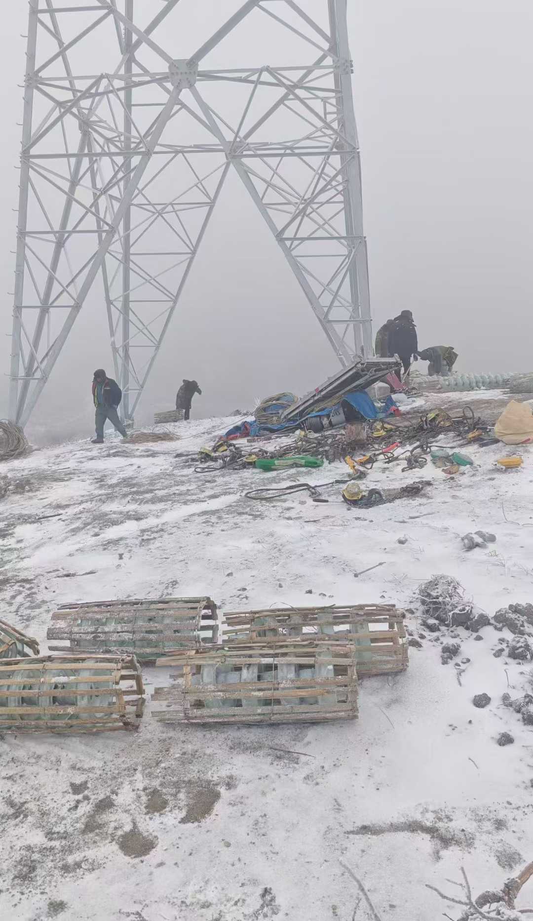
The failure mode of a material is a critical consideration in engineering design, and in this regard, glass insulators have a unique and highly desirable characteristic. When a glass insulator fails, either due to an electrical overload or a mechanical impact, it does not simply crack or deform. Instead, it shatters into a multitude of small, relatively harmless fragments in a process known as self-destruction or self-explosion. This might seem like a dramatic and undesirable event, but it is actually a key safety feature. The complete shattering of the insulator makes the failure immediately and unambiguously obvious to any observer. There is no ambiguity about the condition of the insulator; it is either intact or it is not.
This predictable and visible failure mode is in stark contrast to that of porcelain insulators. A porcelain insulator can develop an internal puncture or crack that is not visible from the outside. This can create a "zero-value" insulator, which is electrically compromised but still appears to be structurally sound. A string of insulators with a hidden zero-value unit is at a much higher risk of a cascading failure, as the remaining insulators in the string are subjected to a higher electrical stress. The self-shattering failure mode of glass insulators eliminates this risk. When a glass insulator fails, it is immediately apparent, and it can be quickly and easily replaced, restoring the integrity of the insulator string. This enhances the safety and reliability of the power grid and simplifies maintenance procedures for high-voltage electricians.
3.5.1 Safety and Predictability
The self-shattering failure mode of glass insulators is a key safety feature that is highly valued by power system operators. This characteristic, often referred to as "zero-value self-breaking," means that any damage to the insulator is easily detectable from the ground, reducing the need for close inspections and enhancing safety . When a glass insulator shatters, the mechanical strength of the remaining insulator string is not compromised, as the glass fragments near the steel cap and pin remain stuck in place, providing sufficient strength to prevent the string from breaking . This predictable failure mode allows for the safe and controlled replacement of the damaged insulator, minimizing the risk of a cascading failure that could lead to a widespread power outage. The ability to quickly and easily identify and replace failed units is a major advantage of glass insulators and a key factor in their continued use in critical high-voltage applications.
3.5.2 Immediate Detection of Faults
The complete shattering of a failed glass insulator makes it very easy for maintenance crews to spot during routine inspections. A missing or shattered insulator is a clear and unambiguous sign of a fault that requires immediate attention. This immediate detectability is a major advantage for power utilities, as it allows them to quickly identify and replace failed units, thereby preventing cascading failures and improving the overall reliability of the power grid. This feature is often referred to as "zero-value self-explosion," meaning that an insulator with zero electrical strength (a "zero-value" insulator) will self-destruct, making its condition obvious. This eliminates the need for costly and time-consuming "zero-value" testing that is required for porcelain insulators to detect internal failures.
4. Decoding the "Blue Glass Electric Insulator"
4.1 The Myth of Blue-Tinted Glass
The term "blue glass electric insulator" often evokes images of antique, cobalt-colored glass insulators that were used in the early days of telegraph and telephone lines. These vintage insulators are now highly sought-after collectibles, and their distinctive blue color was often a result of the specific impurities in the sand used to make the glass or the addition of cobalt oxide as a coloring agent. However, in the context of modern high-voltage power transmission, the idea of a blue-tinted glass insulator is largely a myth. The glass used in today's power line insulators is typically clear and colorless, as the focus is on maximizing its electrical and mechanical performance, and any tinting could potentially affect its properties or make it more difficult to inspect for internal defects.
The modern "blue glass insulator" is not blue in the sense of being made from blue-colored glass. Instead, the blue color is a marking or a band that is applied to the surface of the insulator. This color-coding is a standardized system used to identify the mechanical strength of the insulator. This system allows for quick and easy identification of the insulator's rating in the field, which is crucial for ensuring that the correct insulator is used for a particular application. The use of color-coding is a practical and efficient way to manage inventory and reduce the risk of installation errors, which could have serious consequences for the safety and reliability of the power grid.
4.2 The Reality: Color-Coding for Strength Identification
The reality of the "blue glass electric insulator" is that the blue color is a standardized marking used to indicate the mechanical strength of the insulator. This color-coding system is typically based on standards set by organizations such as the American National Standards Institute (ANSI). The system is designed to be simple and intuitive, allowing for quick visual identification of the insulator's strength class without the need for close inspection or reference to documentation. This is particularly important in the field, where conditions can be challenging and time is often of the essence.
The color-coding is usually applied as a band or a series of bands on the surface of the glass insulator. Each color corresponds to a specific mechanical strength rating, which is typically expressed in pounds or kilonewtons (kN). This system helps to ensure that the correct insulator is selected for the mechanical loads of a particular application, such as a long-span transmission line or a high-tension dead-end. The use of a standardized color-coding system is a critical safety measure that helps to prevent the use of an undersized insulator, which could lead to mechanical failure and a catastrophic power outage.
4.2.1 The ANSI Standard for Color Banding
The American National Standards Institute (ANSI) has established a standardized color-coding system for insulators to indicate their mechanical and electrical ratings. This system is widely adopted in North America and other regions that follow ANSI standards. The color bands are typically applied to the cap or pin of the insulator and provide a clear, unambiguous identifier of its strength class. This standardization is vital for interoperability and safety across different utility companies and manufacturing suppliers. It ensures that an insulator from one manufacturer can be easily identified and correctly used in a system designed with components from another. The ANSI standard covers various aspects of insulator design and performance, and the color-coding is a key visual component of this comprehensive framework. Adherence to these standards is a mark of quality and reliability, giving utilities confidence in the products they purchase and install on their networks.
")
4.2.2 Blue Band: Signifying 40,000 lbs (180 kN) Strength
In the ANSI color-coding system, a blue band on an insulator signifies a specific mechanical strength rating. While the exact value can vary slightly depending on the specific standard and era, a blue band is generally associated with a high-strength insulator, often in the range of **40,000 pounds (approximately 180 kilonewtons)** of mechanical load. This level of strength is typically required for heavy-duty applications, such as long-span transmission lines, river crossings, or areas with high ice and wind loads. The use of a blue band allows a high voltage electrician to quickly identify these high-strength units among a batch of insulators, ensuring they are placed in the most critical positions on the transmission tower or pylon. This visual cue is invaluable during construction and maintenance, reducing the risk of using an undersized insulator, which could lead to mechanical failure and a catastrophic power outage. The blue band, therefore, is not an aesthetic feature but a critical piece of safety information.
4.2.3 Other Colors: Yellow and Red Bands
The ANSI color-coding system includes other colors to represent different strength ratings. For example, a yellow band might indicate a medium-strength insulator, while a red band could signify an even higher strength rating than the blue-banded unit. This tiered system allows for a wide range of insulator strengths to be easily distinguished in the field. The specific values associated with each color are defined in the ANSI standards, providing a consistent and reliable method for identification. This system is not limited to glass insulators; it is also used for porcelain and composite insulators, creating a universal language for insulator strength across all material types. The use of multiple colors allows engineers to design transmission line strings with a mix of insulator strengths, optimizing the mechanical performance and cost-effectiveness of the entire assembly. For instance, higher-strength units might be used at the ends of a string, where the mechanical loads are greatest, while standard-strength units are used in the middle.
Table 1: ANSI Color-Coding for Suspension Insulator Strength Ratings
| Color Band | Mechanical Strength (lbs) | Mechanical Strength (kN) | ANSI Class |
| Yellow | 30,000 | 140 | 52-5H |
| Blue | 40,000 | 180 | 52-8H |
| Red | 50,000 | 222 | 52-11 |
4.3 Practical Benefits of Color-Coding in the Field
The practical benefits of the color-coding system for insulators are numerous and significant, particularly for the high voltage electricians and engineers who work on power lines. This simple yet effective system enhances safety, improves efficiency, and reduces the likelihood of costly errors. In the complex and often hazardous environment of a high-voltage transmission line, any tool that simplifies tasks and improves clarity is invaluable. The color-coding of insulators is a prime example of a low-tech solution that provides high-value benefits, contributing to the overall reliability and safety of the electrical grid. It is a testament to the importance of clear communication and standardization in engineering practices.
4.3.1 Simplifying Material Handling and Inventory
In a utility warehouse or at a construction site, thousands of insulators of various types and strengths may be stored. The color-coding system allows for quick and easy sorting and identification, simplifying inventory management and material handling. Instead of having to read small, often obscured markings on each insulator, workers can simply look for the color band to determine its strength class. This speeds up the process of loading trucks, stocking shelves, and preparing materials for a job. It also reduces the risk of mixing up insulators of different strengths, which could lead to delays and errors during installation. For a large utility company with multiple warehouses and a vast inventory, this system is essential for maintaining an organized and efficient supply chain. The ability to quickly and accurately identify the right insulator for the job is a key factor in keeping projects on schedule and within budget.
4.3.2 Reducing Installation Errors
Perhaps the most critical benefit of the color-coding system is its role in reducing installation errors. When a lineman is working on a transmission tower, often in challenging weather conditions and at great heights, the ability to quickly and correctly identify the required insulator is paramount. A mistake in selecting an insulator of insufficient strength could have catastrophic consequences, leading to mechanical failure, power outages, and potential injury. The color bands provide a clear, unambiguous visual cue that helps to prevent such errors. By simply matching the color of the insulator to the specifications on the engineering drawings, the lineman can be confident that the correct component is being installed. This simple check can save time, money, and, most importantly, lives. The color-coding system is a powerful example of how a small detail can have a profound impact on the safety and reliability of a complex engineering system.
5. Manufacturing Process and Quality Standards
5.1 From Raw Materials to Finished Product
The production of high-voltage glass insulators is a highly controlled and precise process designed to ensure that the final product meets stringent mechanical and electrical performance requirements. The process involves several key stages, from the careful selection of raw materials to rigorous quality control and testing. Adherence to international standards is also crucial to guarantee the reliability and safety of the insulators in the field.
5.1.1 Raw Material Selection: Silica Sand, Soda Ash, and Limestone
The primary raw materials for making glass insulators are silica sand (SiO2), soda ash (Na2CO3), and limestone (CaCO3) . Silica sand is the main component, providing the basic structure of the glass. Soda ash acts as a flux, lowering the melting point of the silica, while limestone acts as a stabilizer, improving the chemical durability of the glass. In addition to these main ingredients, other additives such as alumina (Al2O3) and magnesium oxide (MgO) may be included to enhance specific properties of the glass, such as its mechanical strength or resistance to weathering . The purity and consistency of these raw materials are of utmost importance, as any impurities can affect the quality and performance of the final product.
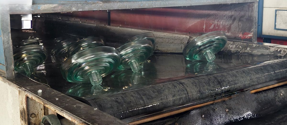
5.1.2 The Melting Process at High Temperatures
The carefully weighed and mixed batch of raw materials is fed into a high-temperature furnace, where it is heated to temperatures between **1,400°C and 1,600°C (2,550°F to 2,900°F). At these extreme temperatures, the raw materials melt and fuse together to form a homogeneous molten glass. The melting process is carefully controlled to ensure that the glass has the correct composition and properties. The molten glass is then refined to remove any bubbles or impurities, resulting in a clear, uniform material that is ready for forming.
5.1.3 Molding and Forming Techniques
The molten glass is then formed into the desired shape of the insulator using a variety of molding and forming techniques. For suspension insulators, the molten glass is typically pressed into a mold to form the disc shape. The metal fittings, such as the cap and pin, are then inserted into the mold and the glass is formed around them, creating a strong, integrated assembly. The forming process is highly automated and precisely controlled to ensure that each insulator has the correct dimensions and shape.
5.1.4 Controlled Cooling (Annealing) to Relieve Stress
After forming, the glass insulators are subjected to a controlled cooling process known as annealing. This process involves slowly cooling the insulators in a special oven, or lehr, to relieve any internal stresses that may have been introduced during the forming process. Annealing is a critical step in ensuring the long-term stability and strength of the glass. If the glass is cooled too quickly, it can develop internal stresses that can lead to cracking or failure later on. The annealing process is carefully controlled to ensure that the insulators are cooled at a uniform rate, resulting in a strong, stress-free product.
5.1.5 Surface Treatment and Finishing
After annealing, the glass insulators may undergo various surface treatments and finishing processes. This can include grinding and polishing to ensure that the insulators have the correct dimensions and a smooth surface. The metal fittings may also be treated with a protective coating, such as galvanizing, to prevent corrosion. The final step in the manufacturing process is a thorough inspection to ensure that each insulator meets the required quality standards.
5.2 Rigorous Quality Control and Testing
The manufacturing of glass insulators is subject to rigorous quality control and testing at every stage of the process. This ensures that the final product is of the highest quality and will perform reliably in the field. The testing procedures are designed to verify the mechanical, electrical, and dimensional properties of the insulators, and to ensure that they meet the requirements of the relevant international standards.
5.2.1 Mechanical Load Testing
Mechanical load testing is performed to verify the strength of the insulators and their ability to withstand the mechanical loads they will be subjected to in service. This can include tensile strength tests, compressive strength tests, and cantilever strength tests. The tests are typically performed on a sample of insulators from each batch, and the results are used to ensure that the insulators meet the required strength ratings.
5.2.2 Electrical Performance Testing
Electrical performance testing is performed to verify the insulating properties of the insulators. This can include tests for dielectric strength, flashover voltage, and leakage current. The tests are typically performed under both dry and wet conditions to simulate the range of environmental conditions the insulators will be exposed to in the field. The results of these tests are used to ensure that the insulators will provide reliable electrical insulation over their entire service life.
5.2.3 Visual and Dimensional Inspections
Visual and dimensional inspections are performed on every insulator to ensure that it is free from any defects and that it meets the required dimensional tolerances. The visual inspection is used to identify any cracks, chips, or other surface defects that could compromise the performance of the insulator. The dimensional inspection is used to verify that the insulator has the correct size and shape, and that the metal fittings are properly aligned.
5.3 International Standards and Certifications
The design, manufacture, and testing of glass insulators are governed by a number of international standards and certifications. These standards ensure that insulators from different manufacturers are interchangeable and that they meet a minimum level of quality and performance. Compliance with these standards is essential for ensuring the safety and reliability of the power grid.
5.3.1 IEC (International Electrotechnical Commission) Standards
The IEC is a global organization that develops and publishes international standards for electrical and electronic technologies. The IEC has developed a number of standards for glass insulators, including IEC 60383, which covers the general requirements for insulators, and IEC 60305, which covers the specific requirements for toughened glass insulators. These standards are widely adopted around the world and are the basis for the national standards of many countries.
5.3.2 ANSI (American National Standards Institute) Standards
ANSI is a private, non-profit organization that administers and coordinates the U.S. voluntary standards and conformity assessment system. ANSI has developed a number of standards for glass insulators, including ANSI C29.2, which covers the specific requirements for suspension insulators. These standards are widely used in North America and are the basis for the procurement specifications of many utilities in the region.
5.3.3 IEEE (Institute of Electrical and Electronics Engineers) Guidelines
The IEEE is a professional association for electrical and electronics engineers that develops and publishes a wide range of technical standards and guidelines. The IEEE has developed a number of guidelines for the application and testing of insulators, including IEEE Std 957, which provides a guide for cleaning insulators. These guidelines are widely used by utilities and engineers to ensure the reliable operation of their power systems.
5.3.4 National Standards (e.g., GB in China)
In addition to international standards, many countries have their own national standards for glass insulators. For example, China has the GB standards, which are developed and published by the Standardization Administration of China (SAC). These standards are based on the IEC standards but may include additional requirements that are specific to the Chinese market. Compliance with these national standards is mandatory for insulators that are sold in the respective countries.